Screenshot from 2023-07-30 13-57-51.png
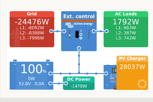
Attached overview is from my ESS what consists of 6 pcs MP2-5000 with individual phase regulation setup. The shown grid feed in is approximately 24kW. This fits to the MP2-5000 datasheet what specifies 4000 W or 5000 VA what requires a cos phi better 0,8.
The AC loads are below 2kW with L2 slightly asymmetric. Battery charge is 100% and charge/discharge should only happen to limit sudden PV power changes to the 400 Watt/sec grid requirements.
A small DC Power symbol shows probably any disbalance from the equation
PV = ACLoad+GridFeed.
From wiring I know, DC Power is always a sink with about 80W LED light plus Windows PC plus Cerbo-GX plus PoE Switch with phone and cameras. As it is certainly no power source, its value should not go negative.
From the moment, the MP2-5000 touch their 4000 Watt limit, DC Power becomes significantly negative. In attached screendump, PV produces 28kW while 24,4 are feed to the grid and 1,8kW go to the AC loads. There seems a gap of
28-24,4-1,8=1,8kW.
Assume the power meassurements are individual per device, I tried to calculate the Multiplus efficiency with the missing 1,8kW by:
100% - 100%*1,8kW/28kW = 93,6 %
what is inside the expected range for a torroid transformer.
The shown DC Power of 1,5kW is similar to the lost 1,8kW but direction is obviosly wrong. I already ordered a smart shunt at my Victron dealer for more accurate DC load meassurements but unfortunately there seems some delivery time for the moment. As long, I cannot explain any reason for the shown 1478 Watts of DC Power what would be a marvelous thing if they were really generated anywhere. At least the animation is wrong in outgoing direction.