question

logic28 avatar image
logic28 asked

Multiplus II Internal Diagram

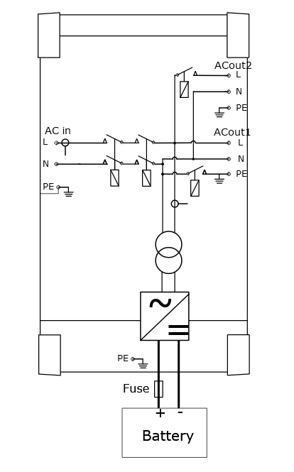
In search of the internal diagram of the Multiplus II 48 5000/70 have noticed various images showing different internal connect/disconnect options.

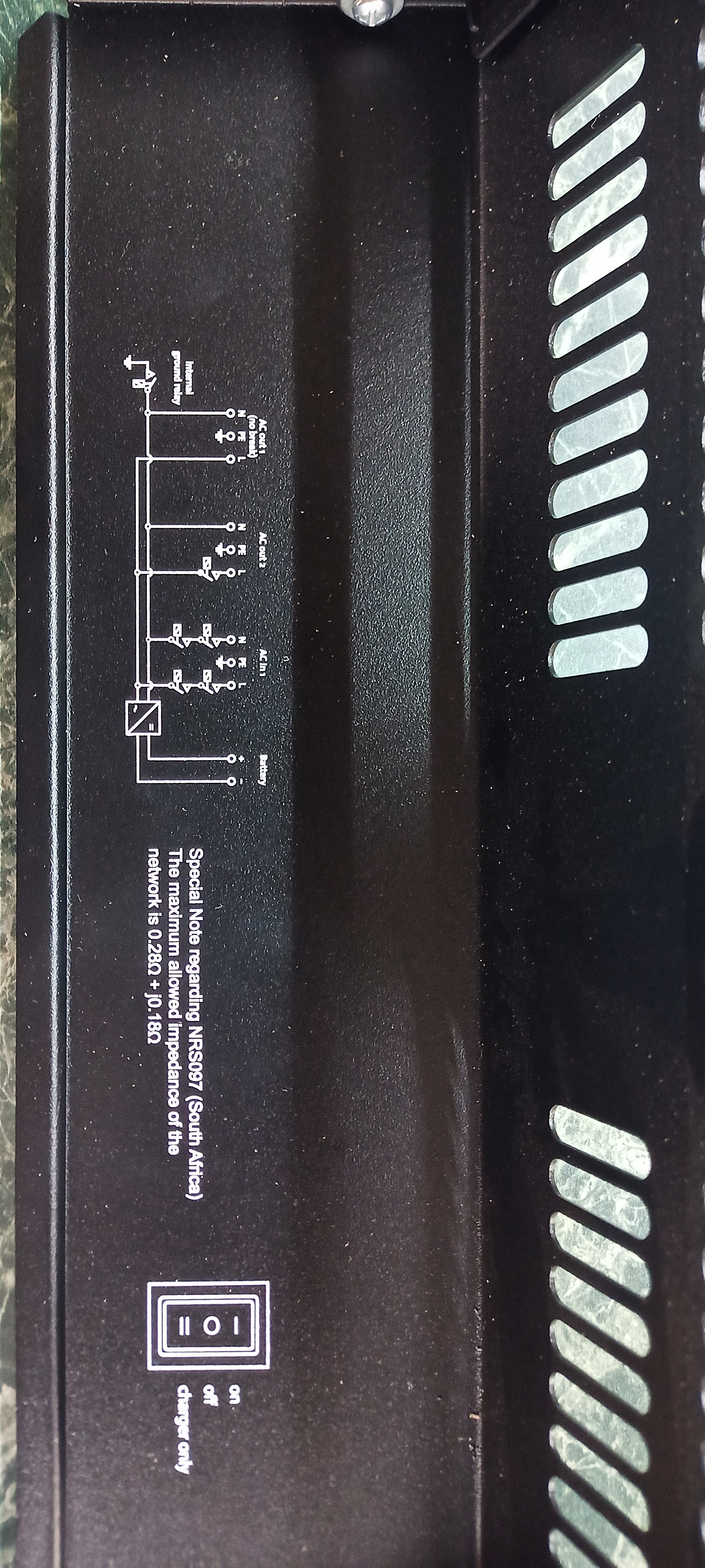
The drawing inside the unit only shows AC1 out disconnect and Ground to neutral lift consistent with the wording of the instruction.

img-20230712-160812-846.jpg

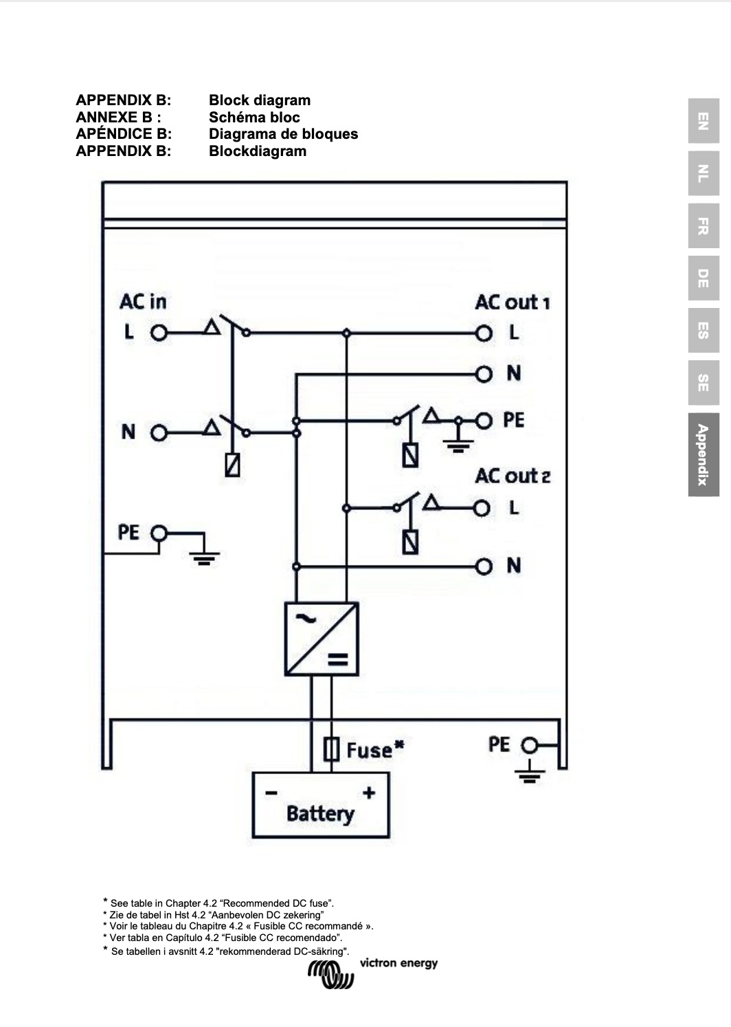
However, on the same model manual, I found a diagram showing ACout 2 disconnecting L and Pe

disconnect.jpg


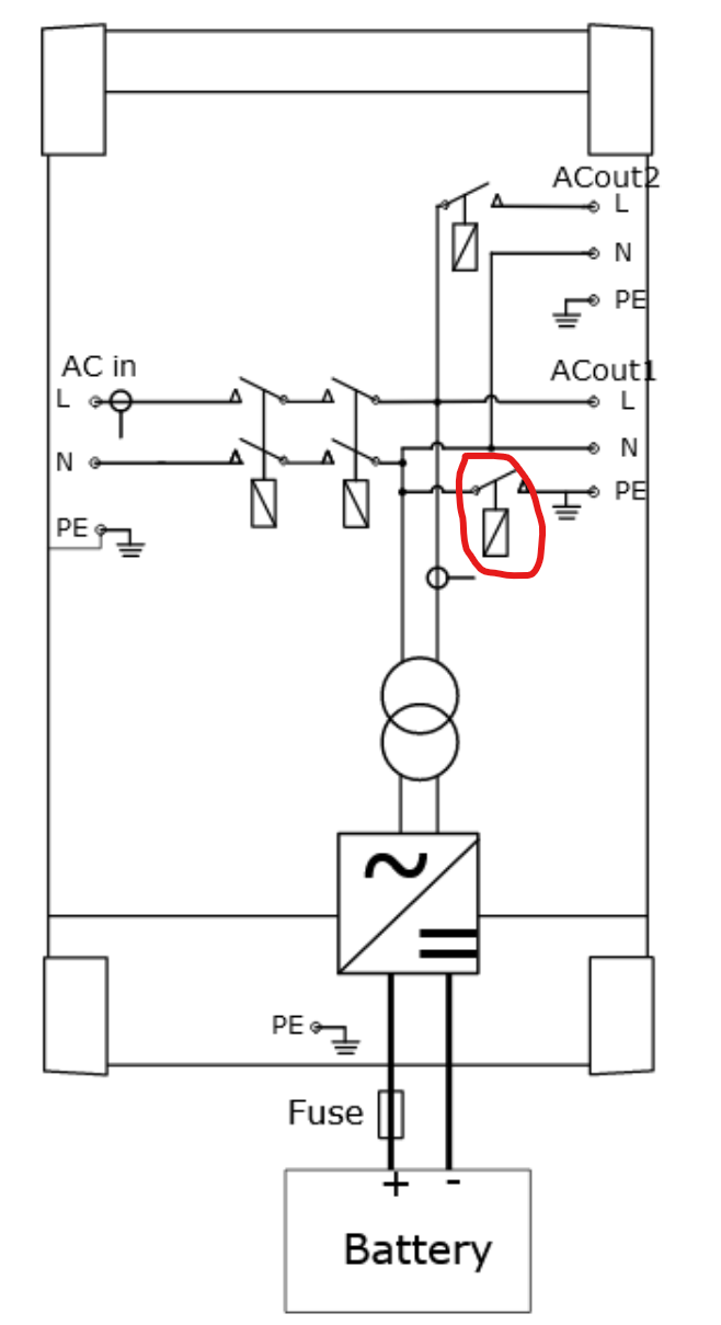
and in another diagram forwarded to me by a member yet another arrangement with AC1 out Pe ground lift.

02-copy.png

What I need is to know if all Pes are bonded to the chassis at all times or if there are situations where one or more gets disconnected from the others.

BTW, if someone is kind enough to explain why Victrons call Pe that way I would be interested.

Multiplus-II
disconnect.jpg (151.4 KiB)
02-copy.png (25.4 KiB)
9 comments
2 |3000

Up to 8 attachments (including images) can be used with a maximum of 190.8 MiB each and 286.6 MiB total.

conkev23 avatar image conkev23 commented ·
All of the grounds/PE/Physical Earth connections according to the schematic are connected at all times.
1 Like 1 ·
conkev23 avatar image conkev23 conkev23 commented ·

hit submit too fast.

The relay that connects the PE to the N is for Nuetral bonding at the source when the unit is in off grid mode.

0 Likes 0 ·
logic28 avatar image logic28 conkev23 commented ·
Yes that is very clear to me but here some are showing the Pe also being disconnected
0 Likes 0 ·
logic28 avatar image logic28 conkev23 commented ·
Thanks, that is what I understand too, however, as you can see from the images, some drawings show that it gets disconnected on the way out
0 Likes 0 ·
Kevin Windrem avatar image Kevin Windrem logic28 commented ·
If you look more closely, all PE connections are connected to a ground symbol. The relay to the left of the ground goes to neutral. This connection is open when on grid and closed when inverting with grid disconnected.

The Multi II does in fact have two AC input relays in series in order to meet some safety requirements.

1 Like 1 ·
logic28 avatar image logic28 Kevin Windrem commented ·
Yes, I've got confused by the different arrangments in different drawings, you're absolutely correct, thanks for pointing that out to me.


0 Likes 0 ·
conkev23 avatar image conkev23 logic28 commented ·

Are you talking about the relay that I circled?
1690316853350.png
If so, that is only for N to PE bonding.

0 Likes 0 ·
1690316853350.png (79.8 KiB)
logic28 avatar image logic28 conkev23 commented ·
Yes, but I can see now that it only disconnects the neutral so it is in fact consistent with my first image directly printed inside the case. My bad, sorry.
0 Likes 0 ·
conkev23 avatar image conkev23 commented ·
as a side note, it is interesting that they printed a complex number for the impedance on the cover. They don't have that in the US version I have.
1 Like 1 ·
0 Answers