Hello, I have an RV with two ceiling A/C units. The onboard Onan 5500 generator has no problem starting and running both A/C units at the same time. I recently installed a MultiPlus II 2x120v 3kVa inverter. Using the MK3-USB adapter I updated firmware to 5.02 and disabled the Power Assist and Dynamic Current Limit settings. I prefer to use the inverter and generator separately and only when needed. Here's my issue. With the MultiPlus in the middle of the AC circuit, I can no longer run both A/C units while only on generator. Even with Power Assist and Dynamic Current Limit disabled, the inverter overloads and shuts down. How do I use the full 5500w of my generator without the inverter intervening and going into overload? Thank you.
asked
MultiPlus II 2x120v with Generator
Your Onan 5500 is only single phase output. Even when the generator is wired as "split phase" output, the phases are not 180 degrees out. The mp2 2x120 will see this as a single phase 120v input and will only pass thru L1 and the L1 and L2 outputs will be tied together. Even though you may have both L1 and L2 outputs connected from the generator, only L1 is being used. Basically your generator is cut in half in this configuration. If the ac wiring from the transfer switch to the mp2 is of adequate size to supply the full output (5500 watts) of the generator, you can connect a jumper between generator L1 and L2 on the generator input side of the transfer switch. This will give you the full output of the generator on L1 to the mp2.
Before the naysayers jump on board, let me say that I own and operate an RV service center and have over 30 years in the industry. These smaller Onans with dual line outputs are not split phase they are actually single phase with 2 windings which are in phase. There is no issue with connecting the 2 outputs together. The larger Onan units definitely do NOT do this, as bad things will happen.
We are also an RV service center that has transitioned to about 95% solar installations and support over the past couple of years.
The simplest way to handle this with Onan dual output generators that output in the same phase (5500/7500/8000) is to use a Victron AutoTransformer. This is exactly what I did on my personal coach which has dual Multiplus 24/3000-70 units installed, this allows both units to charge and take advantage of the full output capability of the generator when necessary.
We wired the autotransformer through the transfer switch so a single MPII 2x120 would also see all incoming generator power as split-phase and would pass through on both legs unlike operation as Derrick properly describes above without an autotransformer.
As Derrick says, went the Multi detects two in-phase legs, it will ignore the L2 input. It will connect the L2 output to the L1 output which is also where the inverter connects. Your generator will not be able to supply the power necessary to start the second air conditioner and its voltage and frequency will both go down. It is possible the Multi will reject the AC input in this case and try to supply the load from the inverter.
As Derrick says, rewire the two outputs of the generator in parallel (with appropriately sized wiring) and connect that to the L1 input to the Multi. If you also have a 50 amp 120/240 shore power connection, wire it's L2 leg to the Multi L2 input and route the L1 shore power leg and the generator parallel connection to a 120 volt transfer switch and connect that to the Multi's L1 input.
Is this a 120/240 volt split phase system or a single phase 120 volt system?
Is the generator 120 or 120/240?
If split-phase, are both air conditioners on the same leg? If so, try moving one of them to the other phase.
Make sure the AC input current limit is set high enough to accommodate your available shore or generator power.
Kevin Windrem, Thank you for the response. The Onan 5500w generator is a 120v type with two 30a circuits. Each leg powers half the circuit breaker panel. The A/C units are split between the two legs. The input current in the MultiPlus is set to 50a. Each A/C unit has its own 20a breaker which has never tripped.
derrick thomas, one more comment. I agree. The generator is single phase 120v. When the generator is ON and the MP2 is in the ON position with "Mains On", I would expect the A/C units to be powered up by the genny only. In my case, both A/C units will power on but they eventually put the inverter in an overload state even when Power Assist and Dynamic Current Limit are disabled. The inverter shuts down for a period of time then tries to restart. Of course, I don't allow it to keep overloading. Does this info change your recommendation? L1 and L2 must be working or both A/C units would not power up.
Are you absolutely certain that when the inverter overload occurs, the inverter is still passing thru current from the generator? It sounds like possibly the inverter is disabling the ac input (possibly due to low ac voltage at the input or something else that the inverter does not like) and the inverter is actually carrying the load, causing the overload.
I would suggest enabling power assist and dynamic current limit, as what you are trying to accomplish is exactly what that is designed to do. If you have a mk3, hookup the laptop and open the monitor in veconfigure. It will tell you exactly what is going on. I am still of the opinion that your issue is how the generator is wired, and the inverter is not able to "pass thru" the full output of the Genny.
Edit to add: L1 and L2 OUTPUTS will ALWAYS be powered regardless of the INPUT configuration (meaning...120 or 240 input does not matter). This is the nature of the 2x120. When a single phase input is detected, (as is the case with your generator) the mp2 will ONLY pass thru the input on L1, and not L2. In this situation L1 and L2 outputs are connected together inside the multi and BOTH are fed from the L1 input.
Got it. Thank you Derrick and Kevin. I will report back.
Kevin - Please confirm I am understanding this correctly. I'm having the same problem, only one leg of the generator is being harnessed always at 50% power when on Gen.
Configuration 50A Shore, Onan 5500 Gen
Can you verify this table is correct and I'm understanding this right?
| Source | Destination |
| Shore L1 | AutoTransferSwitch Shore L1 Input |
| Shore L2 | Multi L2 Input |
| Gen L1 |
AutoTransferSwitch Gen L1 Input |
| Gen L2 | |
| ATS L1 Output | Multi L1 Input |
| ATS L2 Output | ----- Nothing ---- |
No not quite, that's a lot of extra work that's not needed if the RV is already wired CORRECTLY for 50 amp shore power. On a 50 amp rig that has the mp2 2x120 correctly installed and wired for full 50 amp passthru, and also utilizes an ATS before the mp2, simply install a jumper between L1 and L2 @ the generator input of the transfer switch. The jumper needs to be at least the same size wire as the larger of L1 or L2 coming from the generator. (This intended for a 5500 watt generator. Anything over 6000 watts will require a different approach, as the existing wiring most likely will not be sized appropriately.)
Wired this way, L1 and L2 supply from the generator will Ballance the load automatically. There will be voltage present on L2 input to the mp2, but it will not be passed thru the relay. The mp2 knows what to do.
@derrick thomas Hello, I am having a similar issue, but I have an Onan 7500 Diesel in a 1999 Monaco Windsor. I have upgraded my wiring to 6 awg multistrand from the transfer switch to the multi 2.
I have verified that I have 120v on L1, 120v on L2, and 0v between L1 and L2.
My question is can I still jumper the generator L1 and L2 prior to the input to the transfer switch?
You stated earlier that generators above 6000W would need a different approach.
I need to know what that would be?
Thanks.
The main thing is to make sure that the wiring in place will support the load. Qd7500 will most likely be a variable speed inverter generator. (Some of the very early units were constant speed but not many). Depending on what revision the inverter control board is, it may or may not allow you to combine L1 and L2 outputs. It's really one of those "try it and see" situations. The worse that will happen is it will throw an error and you will have to revert back to standard configuration.
More like this then?
| Source | Destination |
| Shore L1 | AutoTransferSwitch Shore L1 Input |
| Shore L2 | AutoTransferSwitch Shore L2 Input |
| Gen L1 |
AutoTransferSwitch Gen L1 Input Jumper Between L1/L2 & L1 or L2 AWG whichever is larger AutoTransferSwitch Gen L2 Input |
| Gen L2 | |
| ATS L1 Output | Multi L1 Input 6AWG Copper |
| ATS L2 Output | Multi L2 Input 6AWG Copper |
Yes exactly, but I must reiterate that this is all dependant upon the ac wiring being of adequate size for the load.
When I connect like this the Onan 5500 will attempt starting, but then goes into fault with Code No 27 - Controller unable to sense output voltage. Then I don't see any AC Voltage at the Multi.
Unconfirmed, but I believe the Onan controller isn't sending any voltage down the line to the ATS while this fault code is present.
How old is the generator? Before installing a jumper did you verify that it is not split phase output by checking for voltage between L1 and L2 outputs? Error 27 usually indicates a bad stator or inverter control unit. This error can show up intermittently if prolonged cranking is required to start the generator (for example after running out of fuel) but in these cases can usually be cleared after allowing the stator to cool down, restart the generator, and apply a sufficient load.
This is on a 2018 Grand Design Momentum. 0 Volts across L1 & L2.
Typical warm start does not require extended cranking, just a 2-3 seconds max.
Removing jumper resolves code 27, but then only L1 and 30 Amps at Multi.
Some of the newer models use the inverter technology which cannot be combined L1 and L2. Most older Onans only use inverter technology on the QD models.
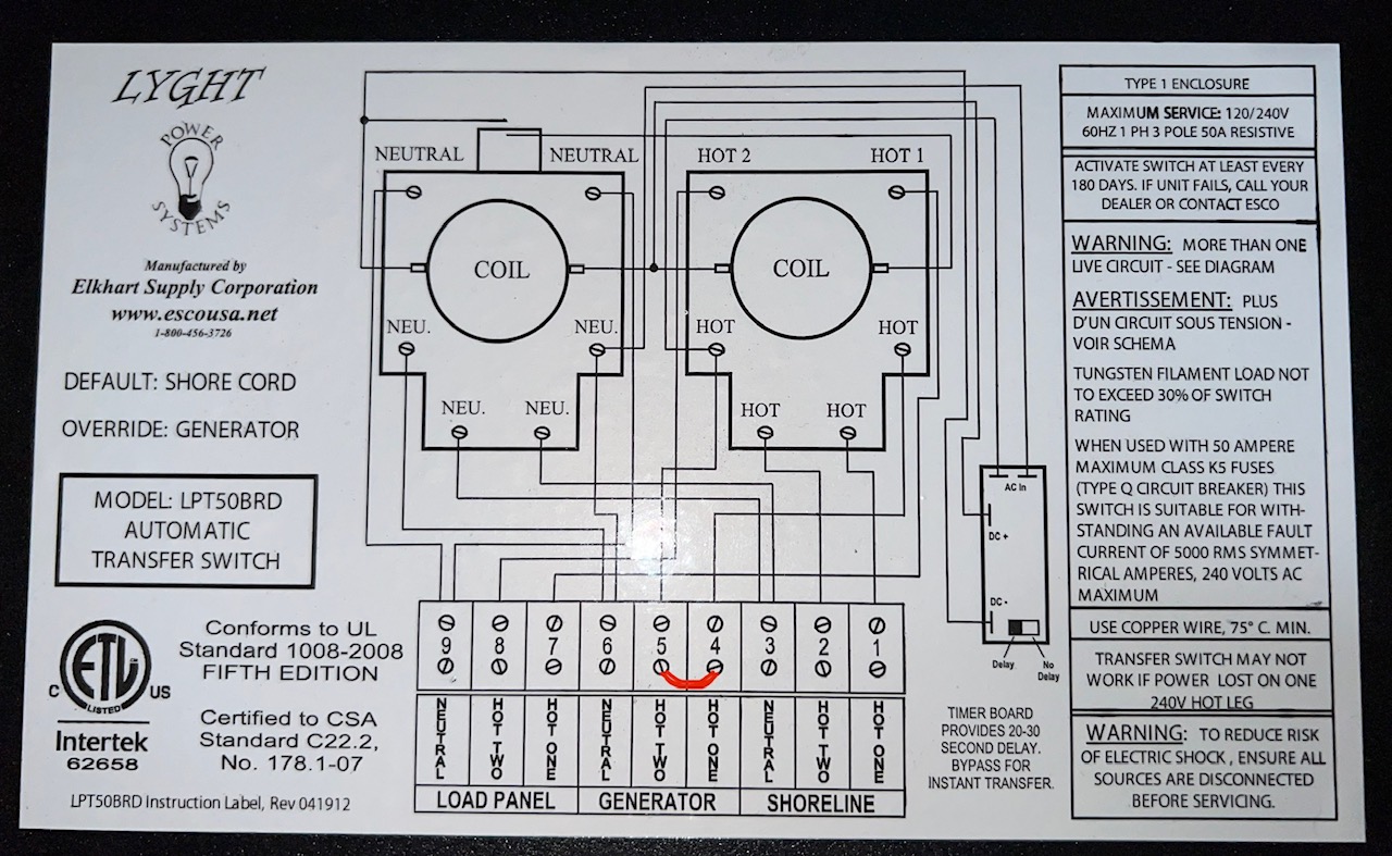
Hi all, I was finally able to jumper the generator L1 & L2 lugs on the transfer switch. (see attached diagram) As a reminder, my Onan 5500 generator has two 30amp circuits in the same phase. Without the inverter I was able to run both A/C units on the generator with no issue. With the inverter, I get L1 overload and shutdown. Unfortunately, I am still not getting the full amps of both circuits to pass through the inverter. Strangely, I see voltage on both legs but no amperage on L2. It still only uses L1 and will not run both A/C units. If I shut down the L1 circuit breaker on the generator, I will get current on L2. I have Power Assist OFF since I shouldn't need it. Any other suggestions? I am beyond frustrated.
The idea behind the jumper is so that the full output of the generator will then be available on L1 to the inverter, L2 will not pass thru on generator because it is the same phase as L1. Enable power assist and dynamic current limiter and that should help with the overload situation when the air con starts.
I will try and report back. Thanks for the quick response.
Also make sure you set the input current limit high enough. I would set it to 37 amps that way your only pulling up to 80% of the rated capacity. Higher elevation and high ambient temperature will also derate the output so take that into consideration.
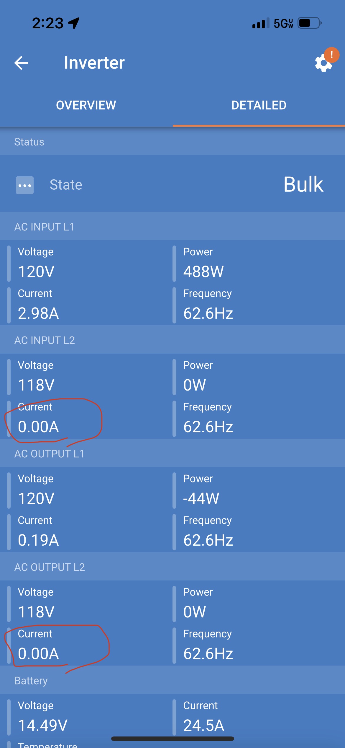
@derrick thomas I enabled Power Assist and Dynamic Current Limiter. The issue still occurs. Once the circuit requires near 30amps it fails with on overload on L1. I took a screen video of the event.
Do you have a MK3 adapter? If you connect to a PC and open veconfigure you can see why the inverter is disconnecting in real time and that would be very helpful in trying to help you troubleshoot your system. I have the same inverter in my RV and I have no problems running 3 ac units.
Yes, I purchased the MK3 and used it for the above screen recording. I will try to get a better recording using veconfigure.
Veconfigure will give you a log of the last few disconnects and the cause. My guess is that it is going to say low input ac, caused by a dip in voltage from the generator because of the startup surge of the AC compressor. What year is the RV and what make/model is the AC unit? You might have to install a hard start capacitor or a soft start unit on the aircon. Dynamic current limiter should help but the startup surge is probably a little to fast for the inverter to catch it. Try lowering the input current limit all the way down to 9 amps and see if it will handle the startup surge, if it does then raise the limit back up to 30 and see if it will carry.
I doubt a "hard start capacitor" will help your issue. But both air conditioner units should be fitted with soft start. I have a MicroAir soft start on mine and the inverter doesn't even notice the startup surge. (I was able to start the a/c without the soft start on inverter but it complained a bit.)
Agreed, the hard start capacitor does help some with inrush current, but the soft start kits are way better. I have the same micro air kits on my units and like you said, the inverter could care less.
I went back and watched the video again and this time I caught the issue. It is definitely the generator voltage dip. It dropped way down and then the inverter disconnected from the generator. On the grid tab of the settings make sure UPS is not selected, accept wide input range is selected, and lower the low voltage disconnect setting.
Can you give a bit more info on what's happening during the video? All I can see in the video is the ac current goes up slightly, the unit switches to invert resulting in a low battery alarm and DC ripple which is caused by the low battery high amp draw. I assume that this all occurs at the time you are switching on the air cond? Do you have "accept wide input range" selected in the inverter config? What are the low voltage (AC) settings? Is UPS unselected?
In the video I recorded the inverter working properly then I switched on a single A/C unit. Notice at 0:28sec the L1 output jumps to 19.72amps which immediately causes an overload failure. I can't seem to get the full amperage of the two 30a generator circuits to L1.
Ok I didn't see that 19 amps in the video but I assumed the switch from shore to inverter was when the AC was switched on. What is happening is you have a high inrush current when the compressor tries to kick on, which is causing a dip in the generator voltage, which then causes the inverter to disconnect the shore power. At that very moment the inrush current is probably somewhere between 40 and 50 amps ac which causes the inverter to overload. Make sure UPS is NOT selected in the configuration as this can cause problems with smaller generators when trying to switch on large loads.
It's hard to be sure from the video but it looks like the Multi is rejecting the AC in when the load increases, then the inverter has trouble supplying the load due to low battery (it's dropping to 9.5 volts!!! I noticed the SOC of the battery drops significantly also.
20 A @ 120 V is about 2500 watts so the inverter should handle this alone. In fact, the Multi is reporting only about 1,400 watts at the time so you are far under the inverter overload.
Indications are you might not have enough battery, or it is weak. It's also possible the wiring is undersized. What do you have for a battery bank?
The Multi would reject the AC input if the incoming power was out of voltage or frequency limits. veconfig may tell you which one it is.
So you have two issues: AC input is rejected; Low battery voltage under load.
I am assuming each AC unit is on a separate leg in the rv distribution panel. I find it odd that it seems the multiplus is not combining L1 and L2 outputs at all. Do you ever see any current on the multiplus l2 output when running other things?
L1 and L2 outputs are connected together when the AC input is single phase, L1 output will show the combined output of both legs. The only time L2 will show any output is when the multi is passing split phase from the input.
okay i wasn't sure if the multiplus showed them separately on the output with single phase input.
@derrick thomas The RV is a 2019 ATC brand toyhauler with two Dometic Penguin II A/C Units. It has a 50a shore power connector. The circuit breaker panel essentially has two haves with the Onan 5500 30a L1 powering the top half with A/C #1 and the lower half powered by the generator 30a L2 with A/C #2. The inverter is wired between the circuit breaker panel and the transfer switch about 12ft away with 6awg wire over the full length. I will probably add hard start capacitors to the A/C units. No doubt it will help. With the generator hots jumpered at the transfer switch, shouldn't L1 be capable of more than 30amps?
Yes, L1 and L2 jumpered at the generator input to the ATS makes the full output of the generator available on L1 to the inverter. The issue is 2 things...the size of the generator (momentary voltage dips during high current startup) and the sensitivity of the inverter to voltage dips on the input. Usually the temporary voltage dip is not a problem because it only lasts for less than a second, but when coupled with higher quality equipment it can cause issues. Making the adjustments I mentioned elsewhere in this thread should alleviate the problems but I would still install a hard start kit as it will be less stressful on the generator and the inverter.
Add soft start units NOT hard start kits. A hard start kit may actually INCREASE the inrush current because it uses a bigger starting capacitor than the one typically stock one.
Soft starters spread the inrush out over time so the peak is much less -- as low as 30% of the inrush current without it.
The soft start is a worthwhile investment, but I don't think it will be the complete solution. As I mentioned above, I was able to start my a/c with my Multi Compact (2000 VA) while inverting without the soft start (with overload warnings).
The soft start may prevent the Multi from rejecting the generator, but the battery voltage sag may still be there. Test this with something like a hair dryer (about 1,500 watts) on high with shore power disconnected. If the battery voltage sags, you need to figure out that problem also.
While I absolutely do agree that a soft start unit is leaps and bounds better than a hard start capacitor, especially when it comes to small generators and inverters, I will say that I have installed many hard start caps for years before the soft start unit was available and every single one reduced inrush current. I have never seen a hard start cap INCREASE the inrush current unless the wrong size had been installed. Hard start caps have been used in RVs for decades.
I mean no disrespect, that's just my personal observation from decades in the field.
I was finally able to get both A/C units running. The UPS setting was enabled so I disabled it. I also did some testing and found that Power Assist must be enabled or the system will fail when the A/C compressors start. Thank you for all the help!
Question: Why is Power Assist required to run the A/C units on generator? The generator would run both A/C units perfectly fine before the inverter was installed.
The voltage dip during startup because of the inrush current is enough that the inverter will disconnect. UPS mode makes the inverter more sensitive to voltage and frequency fluctuation. With power assist and dynamic current limiter enabled, when the AC unit is switched on, part of the load is picked up by power assist and then gradually transfered to the generator making for a gentler startup, preventing the voltage dip. It's doing what it is designed to do.
Thanks for sharing your knowledge on this topic, Derrick.
Question: Does any of this change if I am using Dual(two) MPII 2x120 in parallel?
The only thing that really changes in a parallel setup other than the obvious higher output capacity is that the input current limit is compounded. Meaning that the minimum AC input current limit is per unit in parallel added together. Split phase or multi phase is not however compounded.
So, in a dual parallel inverter setup, we still use the jumper wire from L1 to L2 on the generator side of the transfer switch, still use the same parameters in the programming(no ups, yes dcl, yes power assist, etc). Is this correct?
Yes that is correct. When you parallel Victron inverters together, they become and act as one virtual inverter, so you would treat them as such.
The system as described above keeps giving me ve.bus error 5 Overvoltage on AC-out.
This only occurs when running the onan generator. Otherwise the system works great when inverting and works great on Shore power.
Have you measured the voltage level when running the Genny? Some smaller gens will have high voltage output under no load. Is the generator wired on the input side of the inverters? Not the output side?
Edit to add: If you have added a jumper at the ATS it is possible you have installed it incorrectly. Quick check just remove the jumper and see if the error 5 goes away.
Onan 5500 propane generator. I tested the generator voltage on L1 and L2 to make sure they were in phase. They are.
Generator (and shore power) is wired to ATS. Output of ATS is split into Input of each Multiplus with 6/4 wire. Output of each Multiplus is combined into a 6/4 wire that connects to the power distribution panel.
I have double checked the jumper from L1 to L2 on the generator side of the ATS. It is correct. I used a 6awg wire for the jumper.
It will work when I remove the jumper, but then I only get 30amp max from a 45a generator.
Note.... This error seems to occur when the batteries are taking a full charge(lower SOC). If I test the generator when the batteries are at 90% or above it does not give the error. I need to try and replicate this.
Note.. This exact setup works great with One inverter. I only have this problem with parallel inverters.