question

logic28 avatar image
logic28 asked

Grounding of-grid- grid assisted

We all know that a good grounding for a small group of units yields for units and components bonded at just one main ground rod.

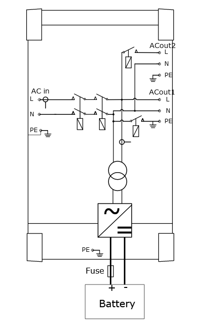
My concern is that if I connect the Multiplus AC in it will automatically join the inverter Neutral/case ground to that of the incoming AC practically connecting two different ground points (house rod and solar shed rod) at a given distance which is wrong.

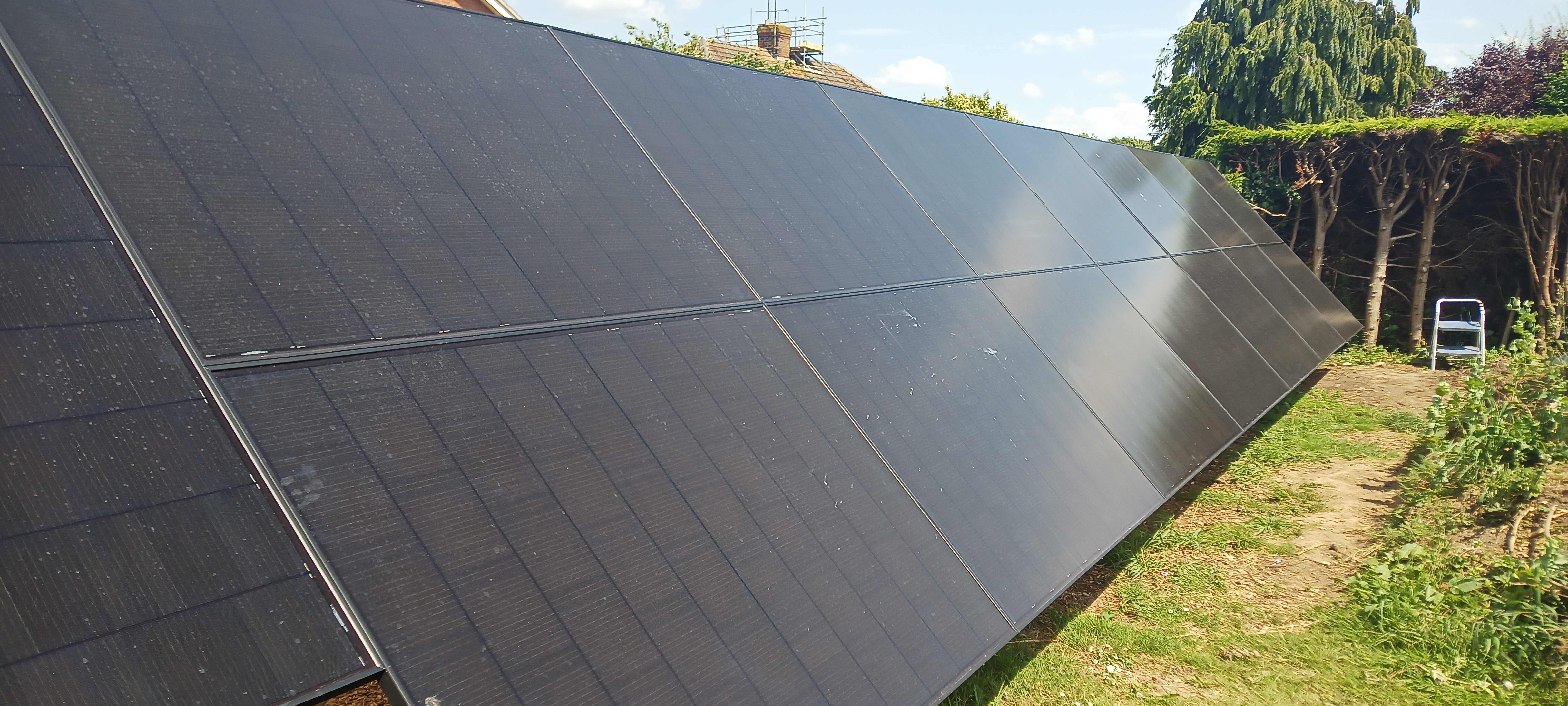
I have already separated the PV ground mount from the solar energy building precisely for that very reason.

How do installers resolve this problem is my question but most importantly what can I do to avoid dual grounding rods?

Grounding
2 |3000

Up to 8 attachments (including images) can be used with a maximum of 190.8 MiB each and 286.6 MiB total.

5 Answers
mvas avatar image
mvas answered ·

You wrote ...

We all know that a good grounding for a small group of units yields for units and components bonded at just one main ground rod.
How do installers resolve this problem is my question but most importantly what can I do to avoid dual grounding rods?

You are misunderstanding basic home wiring.
It is very common, almost required in the USA, to have two or more ground rods.
Typically, we bond the Neutral Bus Bar and Ground Bus Bar at one location,
usually in the Main Breaker Panel.
When a MultiPlus is installed and goes off-grid ...
it Breaks / Opens the connection in the Hot and Neutral wires coming in to the MultiPlus.
Now the Neutral Wire in the house becomes un-grounded.
So, the MultiPlus closes the "Ground" relay.
This action will bond the home's Neutral Wire to Ground, at just one point, inside the MultiPlus.

3 comments
2 |3000

Up to 8 attachments (including images) can be used with a maximum of 190.8 MiB each and 286.6 MiB total.

logic28 avatar image logic28 commented ·
It is very common, almost required in the USA, to have two or more ground rods.
Typically, we bond the Neutral Bus Bar and Ground Bus Bar at one location, usually in the Main Breaker Panel.

That is what I've always thought until I did some research and found this interesting series of video analyses/tutorials from the US that completely disrupted my way of thinking as it makes a lot of sense.

https://www.youtube.com/watch?v=Ypo99VRxT44

Jump to minute 3.09 but the rest is most interesting too.

0 Likes 0 ·
mvas avatar image mvas logic28 commented ·

Yes, I have watched that video. And now I just watched it, agan. This video does not change this fact ... The "active" Neutral Bus Bar is connected to the Ground Bus Bar in one, and only one, location. When I add new Grounding Electrode Conductors (GEC's) then I use an Intersystem Grounding Bridge ...

https://www.mecampbell.com/media/catalog/product/cache/4556987fc6258dfb00e1de307ed01009/i/d/id-pic-v1-gbb5-2.jpg

I connect all of my new GEC's to the original GEC that connects my Ground Bus Bar in my Main Panel to my original Ground Rod. This is done outside of my home. I created a Grounding Array, but still with one, and only one, GEC entering my home = safe. There is no such thing as the house ground rod vs the shed ground rod, because all ground rods, PV Frames and Ground Mount are connected together outside = The Ground Array.

Finally, I run a green ground wire from the Multiplus PE terminal back the Ground Bus Bar in my Main Panel.

When I am on-grid, my neutral wire is only bonded to the Ground Bus Bar in my Main Panel. When I am off-grid, my neutral wire is still only bonded to the Ground Bus Bar in the Main Panel via the ground relay and the green wire. Electrically speaking, my neutral bonding has not changed and there are not any new GEC's inside my home.

I agree, do not wire your house like the picture you posted below.

0 Likes 0 ·
logic28 avatar image logic28 commented ·
When a MultiPlus is installed and goes off-grid ...
it Breaks / Opens the connection in the Hot and Neutral wires coming in to the MultiPlus.
Now the Neutral Wire in the house becomes un-grounded.
So, the MultiPlus closes the "Ground" relay.
This action will bond the home's Neutral Wire to Ground, at just one point, inside the MultiPlus.

Understood, so presumably it will remain closed even when the Multipus is in charge mode only correct?

0 Likes 0 ·
Kevin Windrem avatar image
Kevin Windrem answered ·

Keep in mind that the ground rod is NOT a current carrying connection. The resistance is high. In fact the resistance may not be low enough even to trip a 20 amp breaker. As mias says, there is no issue connecting multiple ground rods to the safety ground network of wiring.

It IS important that all safety grounds in a facility be connected together so that any fault currents can flow to the ground-neutral bonding point and trip breakers. Your PV frame SHOULD be connected to other safety grounds, not isolated from them.

2 comments
2 |3000

Up to 8 attachments (including images) can be used with a maximum of 190.8 MiB each and 286.6 MiB total.

logic28 avatar image logic28 commented ·
screenshot-2023-07-14-at-220729.jpgIt IS important that all safety grounds in a facility be connected together so that any fault currents can flow to the ground-neutral bonding point and trip breakers. Your PV frame SHOULD be connected to other safety grounds, not isolated from them.

That is what I've always thought until I did some research and found this interesting series of video analyses/tutorials from the US that completely disrupted my way of thinking as it makes a lot of sense.

https://www.youtube.com/watch?v=Ypo99VRxT44

Jump to minute 3.09 but the rest is most interesting too.

I have a PV-to-ground bonding cable installed of the same size as the three strings namely 10mm (8AWG) each string thus only sufficient to discharge any static/transient electricity due to wind or else, but if I bond this with the rest of the equipment's ground, as I have seen done so many times, I would effectively create the exact situation that Mike Holt is telling us to avoid since the four Ground Mount metal posts are buried in concrete by 4' across 15m creating in effect a second grounding point at 20m from the primary ground.

Of course, I could have used the posts in concrete as the only ground point for all but I would have to find a way to feed a much larger cable into the underground ducting capable to suit all also due to the distance.


0 Likes 0 ·
Kevin Windrem avatar image Kevin Windrem logic28 commented ·
He is saying for safety against lightening you MUST bond all auxiliary electrons to the safety grounding system in the facility. In your case that means you need to bond your PV support structure to the AC safety ground. If you do not do this and the ground near your array is stuck by lightening, the current from the lightening will flow through other conductors and could damage equipment due to voltage differences between the two earth connections.


I'll be the first to admit that a near by lightening strike is likely to cause damage anyway but the recommendations will minimize any in-building currents.

0 Likes 0 ·
logic28 avatar image
logic28 answered ·
He is saying for safety against lightening you MUST bond all auxiliary electrons to the safety grounding system in the facility.

My apologies for misprinting the time in the video, it is 13.09 where I heard him saying to only ever use one and only one point of reference into the earth. However, he also mentions bonding everything underground together and the same for all above-ground still at only one point of reference into the earth. This is the confusing part but I have to assume that all below-ground being bonded can be considered one point of reference to the earth, am I correct?

For that, as I said before (but not clearly), I have a bonding connection between all my underground items hence the 4 ft concrete encased PV framework and the 8ft grounding rod at the solar shed where all the equipment is installed, cable sufficient for medium currents (8AWG) since, in the event of lightning, the current would travel at a frequency in MHz and for the well known "skin effect" it would travel outside the conductor itself making the size of the cable to a degree irrelevant.

This image shows what I prepared in order to have one and only one reference point.

img-20230715-064204-522.jpgGoing back to my initial concern, if I then connect the grid assist cable to the inverter I would then have a ground rod coming from the house 35m away which is not bonded to the rest of the below-ground items if not for the external conductor itself.
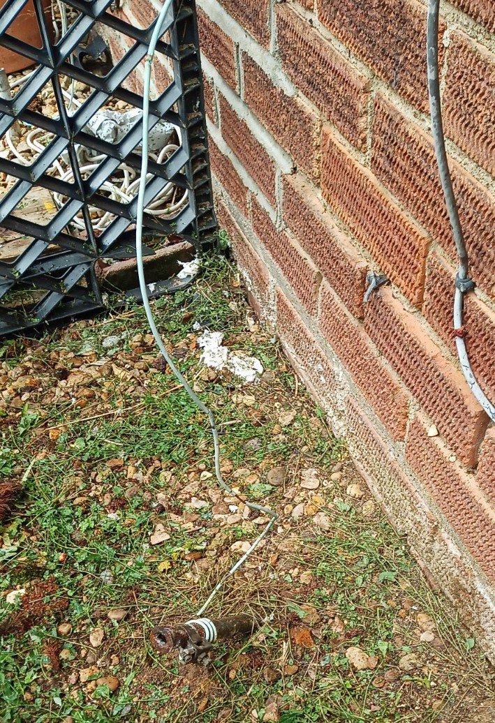
Would that make it wrong?


19 comments
2 |3000

Up to 8 attachments (including images) can be used with a maximum of 190.8 MiB each and 286.6 MiB total.

ejrossouw avatar image ejrossouw commented ·

The latest UK regulations stipulate that for a system that can operate in island mode, you cannot rely on the earth from the grid as it can be severed (e.g. TNCS carries both N & E in a single cable from the substation to your property) and can leave you without any earthing and therefore you have to install a dedicated earth rod for your system.

0 Likes 0 ·
logic28 avatar image logic28 ejrossouw commented ·

Thanks, I have an independent earth rod for my system so I am not worried about my grounding, the fact is that if I wanted to recharge the batteries for testing purposes I might need to draw power from the grid instead of from the generator, so long as it is not a problem, in which case what would I do? Should I just connect live and neutral or would that be wrong too?


0 Likes 0 ·
ejrossouw avatar image ejrossouw logic28 commented ·

I would still use the earth to ensure the safety devices in the house operate correctly in the event of a fault occurring on the line between the shed and house.

0 Likes 0 ·
daza avatar image daza ejrossouw commented ·
@ejrossouw it is now clear OP is not in the UK so I wouldn’t be so quick to advice in that situation unless you know where OP is and there building codes there. Even if OP was in the UK OP mentions generator which would not be able to have combined earth with the DNO in an island mode situation ie grid down supplying own power with DNO earth. For the UK this is a pretty easy rule with just Ireland, Wales, Scotland and England as variables I’ve not looked at the others only England, there are so many states in the US that have there own codes I would be carful around this area as what one accepts not all will
0 Likes 0 ·
logic28 avatar image logic28 daza commented ·

I am indeed in the UK and have been searching for local codes for an off-grid system, I never mention islanding rather everyone else seems to do so. I repeat this is a stand-alone system (Off-Grid) I simply need to draw power, (NOT feed) from the grind at some point for testing purposes. The Victron inverter has its own ground relay to disconnect from the grid when in stand-alone mode however, I am planning to use also a three-way breaker (thus including the earth) on the incoming line that will be closed only when in use so the grid and the solar will be in total isolation during normal operation.

0 Likes 0 ·
ejrossouw avatar image ejrossouw daza commented ·

My understanding is the OP basically wants to run a "long extension" from the house to the inverter and use it as an appliance when it is charging, hence my comment. If his other appliances are all earthed, so should the charger then be. Given there will not be bonding of N&E when used like this, more the reason to ensure the safety devices will operate as intended. I trust he can filter the information applicable given I have been quite clear on that it is the UK rules a refer to, unlike most other generic comments (PS - Ireland is not UK and has their own rules?)

0 Likes 0 ·
daza avatar image daza ejrossouw commented ·

@ejrossouw northern Ireland and all of the devolved governments still have there own rules regarding electrical connections. @Logic28 used US codes so it’s confusing as they do not apply here.

@Logic28 the Victron is by directional even if AC in is only used if it over produces the rest goes to the grid.

Victron does indeed disconnect AC2 out in a grid down but when the grid is on and you have surplus or a load gets switched off that over production will go to the grid.
That being said I don’t know if the ESS in the Victron will be the solution to not feeding back to the grid and I have no idea how reliable that would be.

@Logic28 any how you connect to the DNO this is not an off grid installation but a grid backup and will require DNO application ie you intend to charge the batteries if the solar is not producing enough this would be an additional demand on the grid and they will need to factor it in to see if the grid/sub station has that capacity to supply the additional power.
I would suggest actually talking to your DNO regarding this for absolute clarity around this.


1 Like 1 ·
ejrossouw avatar image ejrossouw daza commented ·

@daza Ireland is not NI as per your original post. :) I actually have customers in all of those places you mentioned including NI. I disagree as you can configure the system as an appliance without a grid code and no feedin or even only enable the charger. This is much the same functionality as with camper vans etc. using shore supply or to charge from it when available. If you use the ACOUT only to supply the loads and no ESS / grid code, it will not feed in. I also disagree with the demand aspect as the UK houses typically is provided with a 63A or lately 100A supply, which is what the DNOs actually cater for. This is even reflected in the latest decisions for the revised G98/G99 fastrack process. They do however have an interest in systems that feed in as it has an influence on the network, however again only over 3.68kW. Maybe YOU should reflect on your ealier remark "... I wouldn’t be so quick to advice ..." The below system is used as an off grid system permanently hooked up to the grid supply.1689505360229.png

0 Likes 0 ·
1689505360229.png (38.4 KiB)
daza avatar image daza ejrossouw commented ·

@ejrossouw lol I ment Northern Ireland I am aware you can see it that’s why i didn’t change the original post, you have customers in all the locations are the building regs the same? As it’s like you are implying it’s the same through out or just a little dig for the NI thing I can take that. What advice have I given is the mention of earthing needing to separate from the DNO wrong?That would be a NO! Advicing OP to speak to DNO for clarity that could be bad advice maybe that was it?


The DNO may provide a 40 63 80 or 100 fuse on single phase this is not demand but potential which can be maxed out as it is additional load that hasn’t been calculated ie the house now batteries over sustained period. akin to EV’s or heatpumps with high electrical demand! If we used your example they don’t supply the grid either but the DNO must be notified.

I would go out on a limb in thinking the grid compliance code is for connections to the grid and anything connecting to the grid should have it.

just because it can be done does not mean it should be done!

You seem to have taken it personally apart from connecting to the grid without notifying of potential additional demand on the grid only thing I’m in disagreement.

EV and Heatpump market are finding this out regards to fuses and linked supplies, this could be one of the reasons why the DNO is to be notified of connecting high loads to the grid but you to you mate. We can agree disagree it doesn’t mean Jack unless you are going to say you are a DNO i fall and bow to your awesomeness ;)

0 Likes 0 ·
ejrossouw avatar image ejrossouw daza commented ·

The information I shared is readily available, but I will move on as we are off-topic. PS - "The maximum value of 60 Amps has been selected for criterion (b) to align with the smallest common DNO cut-out fuse. This also considers the threshold for connecting electric vehicles
and heat pumps without prior application." No speculation required.

1 Like 1 ·
logic28 avatar image logic28 ejrossouw commented ·
The below system is used as an off grid system permanently hooked up to the grid supply.1689505360229.png


I could not find an internal wiring diagram for the Multi so I'm not sure what happens when the earth is disconnected from the N, I assumed, and the tester seemed to agree, that all PEs are still connected with each other so the incoming grid would be bonded to the local Grounding Terminal/electrode.

That is the reason for my initial question which was raised by what I've heard about different potentials in excess of 100.000kv that can exist between two unbonded ground points even at a distance of 19m in the event of lightning striking the earth.

Of course, if in the future, after having discussed with the DNO, I permanently connect to the grid and the grid ground (now 10mm square) is connected to the ground terminal/electrode, I would effectively have bonded all ground points correct? But a 10mm cable would only offer a return path to N for a limited current correct?

So the next question to an installer would be, what size ground conductors are used in the UK to join different ground rods when they exist? Or are they not concerned about bonding them? In this case, any current may find a return path through equipment or other appliances with potential damage.

At the front of my house, the flimsy connector to the ground rod can't be more than 4mm the electrode being almost ridiculous but I suppose in my area, not far from the sea and with such a shallow water table anything would do, or did, back in the day when the house was built.


img-20230719-132614-049.jpg


0 Likes 0 ·
logic28 avatar image logic28 daza commented ·
any how you connect to the DNO this is not an off grid installation but a grid backup and will require DNO application ie you intend to charge the batteries if the solar is not producing enough this would be an additional demand on the grid and they will need to factor it in to see if the grid/sub station has that capacity to supply the additional power. I would suggest actually talking to your DNO regarding this for absolute clarity around this.

Excellent, thank you for your very clear input.

Not having fired up the Multi I'm not sure if you can prevent the inverter from feeding back or not.

However, I have a "grid in" disconnect (including the earth) in the main panel and I was thinking of only connecting at night in the event I needed to charge and, since the house is only using 300wh max during that time, I didn't think it would have an impact on the grid substation, especially if I limit the current to about 30A (we have something in the region of 19kWh supply here)

Having said all this, as I haven't got much time now, I will not connect to the grid for the time being and talk to the DNO first should I decide to do so in the future.


0 Likes 0 ·
logic28 avatar image logic28 daza commented ·
 @Logic28 used US codes so it’s confusing as they do not apply here.

I am after physics first more than rules in order to decide what is safest then I see what the best compromise between the two is in order to keep everyone happy.

I have been searching for the same info in the UK but nothing technically specific was found so far.

0 Likes 0 ·
ejrossouw avatar image ejrossouw logic28 commented ·

I'd suggest you configure your system with grid code "none" and no ESS to ensure the inverter will never operate when the grid is connected to e.g. charge batteries or allow passthru and with no risk of ever feeding back power to the grid. It will basically be an appliance with energy flowing only in one direction. No DNO involvement necessary as you have either 60A or 100A domestic fuse with potential you can use as you see fit. I disagree on the point raised elsewhere unless I see hard evidence to the contrary. Also, imagine campers suddenly having to notify/apply to DNO's because they want to charge their house batteries.

Also, consider getting in touch with an off-grid specialist for the best advice regarding earthing of an off-grid systems as it definitely is not just about hammering a spike into the ground to put it simply. Diagrams are available in the manuals.1689877459538.png

1689875242528.png


0 Likes 0 ·
1689875242528.png (24.6 KiB)
1689877459538.png (25.4 KiB)
logic28 avatar image logic28 ejrossouw commented ·

Thank you kindly for your comments and yes I agree, grounding and bonding its not just as simple as . . . I have researched a lot both in England and in the US as you might have noticed and my house seems to be on the TN CS type which I'm familiar with so I have a strong return path to N at the house. screenshot-2023-07-20-at-215752.jpg

However, I spoke to an Off-Gris specialist a few days ago and I'm expecting a call tomorrow in order to arrange for their visit so that I can discuss with them various points including grounding.

The Victor diagram image that you kindly provided for me is consistent with the one inside the unit itself and only shows all PEs bonded to the metal casing so the moment you connect to ACin, inevitably the grid earth would be joined with that of the installed system.

I've decided to introduce a "ground- Lift" isolator as well as phase and neutral for the ACin line in the main panel so I can always change my mind either way.

Thanks again


PS) I was actually after the full internal wiring diagram of the unit as I normally do for any electronic equipment in case of a problem.

Also, I never understood why they define the unit earth as PE


0 Likes 0 ·
mvas avatar image mvas commented ·

What is stated in the video is not confusing. In my previous post I added a URL link showing how all of the external GEC's are easily combined at one point. Exactly per the instructions in the video. And that video is now somewhat outdated, due to newer NEC regulations. We use an "Intersystem Grounding Bridge" which is UL approved in the USA. Nothing homemade, is allowed. Maybe, you need to post a wiring diagram.

I do not understand this: "... Grid Assist Cable ..." What is that? There is an AC IN connector (wires from your main panel) and an AC OUT connector (wires to your loads) on the Multiplus.

Are you mounting your Multiplus, 35 feet from your house? 35 feet of AC wire from the house and then 35 feet of AC wire back to the house? So, you are adding a total of 70' Feet of high amperage wire between the Main Panel and your loads? Voltage Drop?

We mount the Inverter adjacent to the Main Panel = extremely short / fat wires.

0 Likes 0 ·
ejrossouw avatar image ejrossouw mvas commented ·
My understanding is the OP only requires the AC from the property to charge the batteries occasionally and it is some distance away.
1 Like 1 ·
logic28 avatar image logic28 ejrossouw commented ·
That is correct, thanks
0 Likes 0 ·
logic28 avatar image logic28 mvas commented ·

Let me explain,

1) the inverter and MPPT together with linx power in, linx shunt, linx distributor and batteries are housed in the purposely constructed solar shed double insulated with climate control.

2) the ground mount is at the end of the garden the house in the front (35m away) and the solar shed somewhere in between.

3) the system is designed to feed my 20m long garage/workshop as an Off Grid totally independent from the grid.

4) Victron defines the use of the Multi connected to an external source (AC in) as “power assist” as most users will also use the grid or a generator to add more power if needed; this is not what I am doing instead possibly use the AC in for charging batteries should I need for testing purposes with a disconnect to isolate live neutral and earth.

5) all cables have been calculated to be equal but in most cases over the rated ampacity according to their length.

So my only issue here was what do I do with the grid earth in the event that I should connect it to the Multiplus II to draw power from the grid (not to feed) since it would effectively crate a second grounding point at the house where it has a grounding rod even though is more of a joke, a piece of tubing of unknown length with a flimsy thin wire going inside the building.

The Intersystem Grounding Bridge is effectively a ground bus bar and I have a very large one in the image posted earlier.

It is inside because my rod will come from the ground next to the ducting from the suspended floorimg-20230625-134947-847-copy.jpgscreenshot-2023-07-11-at-180247-copy.jpgimg-20230623-170001-271-copy.jpgimg-20230627-142850-116-copy.jpgimg-20230428-163831-971-copy.jpg

0 Likes 0 ·
daza avatar image
daza answered ·

@ejrossouw correct this all started around EV’s and hot tubs and has been pushed more as DNO’s start to walk away from providing earths going back to old school the introduction of foundation earthing at some stage but it’s unclear if @Logic28 is in the UK I’ve not seen much if any grounding on rails for solar on a roof, one thing they have introduced is DC surge protection for the DC side bring this inline with the AC side well at least in the UK. As to two earthing points be careful and make sure you abide by your regs for distance and placement as the last thing you want is it jumping from one rod to the other

2 comments
2 |3000

Up to 8 attachments (including images) can be used with a maximum of 190.8 MiB each and 286.6 MiB total.

ejrossouw avatar image ejrossouw commented ·
The earthing of the PV frames as far as I am aware is to solely serve in the event of highly unlikely lighting strikes when looking at the UK. Indeed I am aware not even on commercial installations in the UK is it used I was told by professional installers.
0 Likes 0 ·
logic28 avatar image logic28 ejrossouw commented ·

I don't think the PV ground or anything else would provide any adequate lightning protection but more like dump any static electricity generated by wind or something else.

However, as you can see from the image above, I have installed three surge protectors next to the fuses (and they need a grounding point) followed by the breakers and finally by the disconnects, one per string, in order to isolate each line if needed.

Three more isolators are placed at the receiving end in the combiner box with a further surge protector for any potential surge downstream from the PV array (lightening striking the earth creating a spike in the line)

This three strings independent lines system allows me to disconnect one or more strings from inside the shed for servicing as well as enabling me to run a much larger set of individual cables which will more than cope with the length and for a larger current should the PV provided more than rated (general rule multiply the amperage by 1.25) My case each string 12A x 1.25 = 15A

So I run 6 x 10mm wires plus earth.

Reference Method B (enclosed in conduit on a wall or in trunking etc) 10mm = 57A

I only have 15A each

0 Likes 0 ·
mvas avatar image
mvas answered ·

Here is the NEC review explaining what I have been telling you. A single Green EGC, Equipment Grounding Conductor, connects between the Inverter PE and the Main Panel Ground Bus Bar. While ALL of the GEC, Grounding Electrode Conductors, (usually bare copper) for PV Frames, Metal Rack, PV Ground Rods, etc connect together outside of the house. NOTE: We do not connect the Inverter to any GEC (Ground Rod). Same goes for every other device in your home. You do not add a ground rod to your washer, dryer, stove, hot water tank, furnace etc. They are ALL grounded via the Green EGC wire, back to the Main Panel Ground Bus Bar. The same applies to your Inverter. The Inverter does not connect to any existing Ground Rod or any optional PV Ground Rod. The Inverter is ONLY grounded via a Green EGC Wire back to the Main Panel Ground Bus Bar, exactly like every other metal appliance powered by your Main Panel.

https://youtu.be/cZo8ict33_I

All PV Frames, Metal Racks and optional PV Ground Rod ( was required by my inspector! ) was connected with a Bare Copper Wire which then gets bonded back to that Bare Wire, by your AC Meter, between the two AC Ground Rods and your Main Panel. I have a "Grounding System", with all wires GEC's connected outside of my house.

If you add a PV Ground Rod and you decide to connect it your Inverter PE, via a bare GEC then that becomes your "problem". It will work. It may, or may not, be a problem when lightning strikes. We don't do that.

The National Electric Code has finally realized and admitted that adding an extra PV Ground Rod and bonding them directly to the Inverter, can be more dangerous.

3 comments
2 |3000

Up to 8 attachments (including images) can be used with a maximum of 190.8 MiB each and 286.6 MiB total.

logic28 avatar image logic28 commented ·
If you add a PV Ground Rod and you decide to connect it your Inverter PE, via a bare GEC then that becomes your "problem". It will work. It may, or may not, be a problem when lightning strikes. We don't do that.

That is exactly what my question was about and that is exactly what I intended to do but mixed opinions came about reading.

My PV is grounded for static electricity or induced currents and, in my case, for the delivery box surge protectors (I combine at the shed), no bonding between the PV and main panel ground busbar where all the equipment connects to one central point to then reaches the Ground via the ground conductor.

That said the PV is naturally grounded by the encased concrete base so it becomes a "below-ground earth point" which, as I understand from the video, should be bonded to any other underground electrodes in order to avoid unwanted current flowing through the equipment cable potentially damaging whatever they go trough (inverter etc)

I laid the grounding cable between the PV and the shed just in case so that I can connect if I decide to do so.

However I'm not connecting to any meter, and I'm not near the house so these instructions do not exactly apply to my case and I would very much like to see what the NEC would advise for Off-Grid System.

Even though I'm not in the US I very much appreciate how things are handled there


0 Likes 0 ·
ejrossouw avatar image ejrossouw logic28 commented ·
Very nicely executed setup and I like the use of a dolly wheel "jack" as tilting adjuster for the arrays? I have limited insight on the lightening topic other than to date not personally seen any media on solar panels being struck by lightening. Just thinking out loud. DC does not have a reference to earth as with AC systems and as such, unless e.g. your RCD at the house rated for AC/DC current, feeding any back via a combined earth may actually compromise the functionality of the protective devices.
0 Likes 0 ·
logic28 avatar image logic28 ejrossouw commented ·

Yes, that is why I only connect the PV to ground locally in order to discharge potential extreme currents through the surge protectors.

About the jokey wheel jacks (LOL) I could not find anything readily available in the UK so I came up with this temporary solution and in the future perhaps install electric actuators automatically adjusting daily or weekly

However, in order to use these I had to apply a couple of modifications that I can share here if someone is interested; the major one being the need for a bush in which the piston runs into otherwise shaking like hell with any wind. Now I have a firm and precise adjustment.

img-20230302-163905-987-copy.jpg

Also as I'm only using one of the two arms that normally holds the wheel, I've introduced a bushed spherical joint again allowing for precision and flexibility.

All tilting framework on large bearings for good support, none of that one-bolt nonsense I've seen used by installers img-20230127-135944-935-copy.jpg

so to guarantee continuity I made four flexi-grounding conductors

img-20230711-131856-531-copy.jpg

the red compound is copper grease


0 Likes 0 ·

Related Resources

Additional resources still need to be added for this topic