We have installed several system as the below map. Some systems have been working correctly some else, when restart, were failed. who could help us?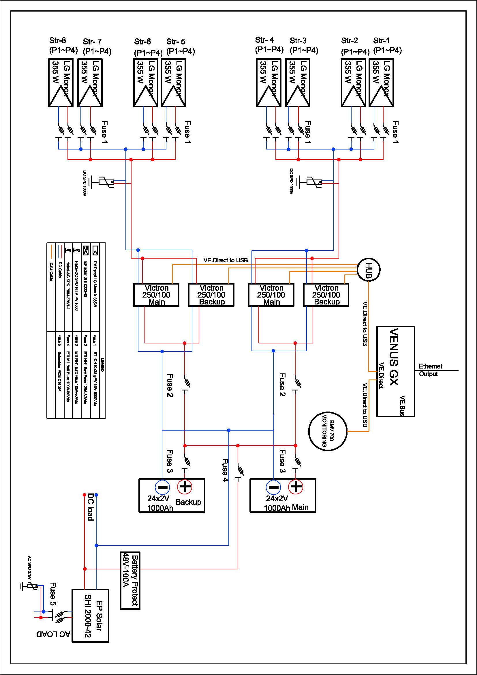
asked
connect multiple MPPT 250/100 to two same battery banks
The main problem you have there is that the same panels feed 2 mppts. Each mppt must have it's own panels. The mppts 'track' to determine the best V, and to have 2 on the same panels is counterproductive. Especially on a restart when both are deliberately applying a wide V range several times, they are likely to interact and not work well.
How you're working the 'Backup' ones though isn't clear.
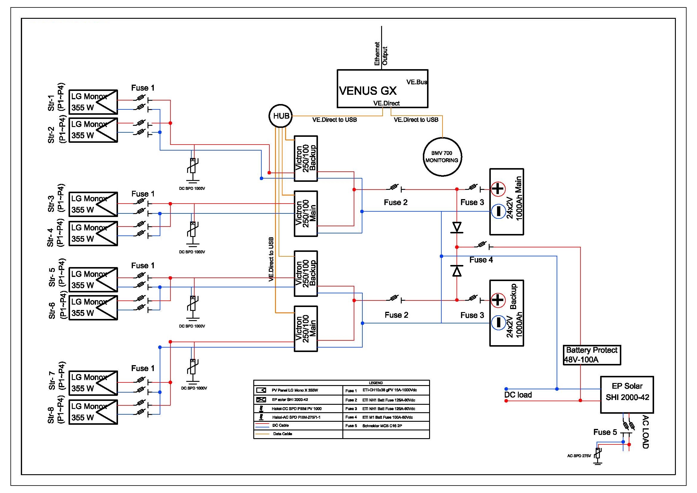
Thank you. If that diagram will be changed to the below diagram, will the problem solve?
@Farhang Hassani
Yes, that's better.
I see you've also added in some diode symbols between the batteries. I was wondering about that too, but that has no bearing on the mppt issue.
When the chargers was faild, It seemed, there was reverse current between 2 battery banks.
It's quite unusual to have side-by-side mppts for redundancy, as they are so reliable.
In your original diagram it's probably possible to disable the 'Backup' units by removing the jumper across their Remote terminals, so then the Main units can operate without interference from 'fighting' trackers. You haven't given much information though on what your problem really is, so it's difficult to help.
Thank you for your response.
What informations are needed to help us?
If one MPPT can handle 4 of those strings, remove the "backup" MPPTs and keep them in storage as spares (or use them in other projects).
Thank you.
If we have to use 4 charger for each system, will the second diagram work correctly?
Wire each MPPT to the busbar (assuming you have a busbar), with a fuse for each positive wire (properly sized) (so four "Fuse 2").
Take the DC loads from the same busbar, not from the inverter. With a separate fuse for the DC load positive wire.
I don't know what's with those diodes you added in the revised diagram.
Make sure that the batteries are equally charged.
The diodes are added, because It's seems, there was reverse current between 2 battery banks.