Why are DVCC charge limits ignored when enabling DC Feed In?
asked
DVCC - FeedIn
It is clearly explained in the DVCC section of the Cerbo/GX manual, footnote 6:
6) DVCC charge current limits are not applied to DC MPPTs when ESS is enabled with Allow DC MPPT to export. This is to get maximum output from the solar panels for export.
I read manual, but I dont understand why victron support team cant change configuration or update FW when fix this option?
Likely because it is more complex than you think it is. Everything cannot be fixed with firmware, sometimes there are more moving parts involved that it appears on face value.
If it was that simple, it would have been done already.
Can be. But if that's the case, it was good to pay attention to it. If it is a hybrid system, then this should be resolved. I can't imagine that someone has 20kW solar panels and a 5kW battery pack. Due to this missing function, the batteries cannot handle only a few charging cycles because it will be destroyed by the high charging current. The solution would be for the converter to limit the charging current if there is no connection to the BMS of the battery, even if h FeedIn is turned on.
with correct battery sizing, this should not be an issue.
But i agree in some way.
There should be an additional parameter:
if selecting DC-feed-in ON, there should pop up an additional parameter, asking:
ignore CCL from BMS: yes/no
I hope Victron will implement this in future.
Why would you set a current limit with a smart battery? Mostly irrelevant in that use case.
Main problem here would be, for example, that the DC from the mppt needs to be changed to AC. It passes over the terminals where also the battery is attached.
If the battery is the easiest path they go there, if the AC is the easiest path that's where they go.
The battery itself would need a way to refuse charge without disconnecting.
You can also cap voltage so the battery does not actually get full and can take overshoots.
Most efficient way to feedback is still AC PV on the input/grid side of the inverter.
Its not that complicated.
I know of applications, where an external control tweaks CVL down via Modbus, until the BMS-CCL is met.
simple as that. And it works well.
This reduces feed-in power, but that is clear. But there are installation that need this feature to protect their batteries.
Victron could easily do, if they would like do
Ignoring feed-in. Smart batteries wouldn’t usually have a charge limit set in DVCC, and that same energy is passing the battery to serve loads on AC out. The physics doesn’t change much because of feeding-in..
not really sure, what you mean?
For my understanding:
If a BMS sends out a charge current limit (CCL), it does not want to see higher current flow into the battery than this limit. Why do you want to ignore that?
If DC-feed-in is OFF, Victron respects this CCL from the BMS.
It looks at CCL from DVCC and CCL from BMS and uses whichever is lower.
If DC-Feed-in is ON, the Multis still respect the CCL from DVCC and BMS, but the MPPT´s does not. They can produce as much as they are capable of.
In my opinion it should be configurable, if the MPPT´s also respect this limit or not.
It is still OK if the MPPT´s provide more current, nobody has any problem with that. But anything higher than BMS-CCL, should then be fed into grid or serve AC-loads, but not flow into the battery.
If the Multis have not enough inverting power to accomplish that, Voltage needs to be lowerd.
I don´t see anything wrong with that.
Important would be, to have it configurable.
But sadly Victron does not offers us this option
CCL isn’t ignored. Only the manually set dvcc charge limit is ignored. Something that isn’t normally set for a managed battery anyway.
oh, you are wrong. Also CCL from BMS IS IGNORED by MPPT´s if "DC-Feed-in" is ON
Nonsense. Usually a dvcc limit isn’t set, yet mppts produce full power so they can service loads AND meet charging needs.
I have no charge current limit set in dvcc (as should be the case) and with ccl=0 the mppts pump power into grid and loads with nothing going to battery.
have really tried this?
it is NOT the way you are saying!!!
I do tune this every day, so i know very, very well:
if you set in DVCC CCL to 0A
-> then the Multis charge nothing into the battery, correct
-> but Smartsolar MPPTs charge all they can into the Battery!!
(if DC-Feed-in is ON)
but if DC-Feed-in is OFF, then also Smartsolar MPPTs charge nothing into the Battery!
CCL of 0A = do not produce.
So saying feedback yes, then don't ignore the battery means the battery stops production. If you want to feedback this is a conflict.
Size the bank correctly and this is not an issue.
Limiting your feedback yourself to within your system capablity is also an option.
Again think about the way the system is physically connected, it means that the DC from MPPTs can not be physically routed up or down since power moves to the path of least resistance. So if that is your battery (with lithium this is usually the case) that is where it goes. It would have to be the battery that has to refuse the charge somehow physically. Disconnecting is not really an option.
i don´t exactly understand what you are talking about?!
sure DC from MPPT´s can be "routed". Why do you think this isn´t possible?
The Multis need to take the DC power available, invert it and use it for AC-grid feed-in or to serve AC-loads.
If the Power from the MPPT´s exceeds the Multis capabilities, the MPPT´s simple must be throttled. Whys should this not be possible?
They can do the very same, if you disable DC-Feed-in
Again:
it would be an easy task for Victron in my opinion, if they would want to support it
You have completely misunderstood how this mechanism works.
If it didn’t work there would be many unhappy users.
I am one of the not happy customer with exactly the problem pedaaa mention. I have sadly bought too many mppt able of charge 200A from my 7.2kWp PV. This is not good for my battery and also not necessary to charge so extreme since most have several hours to charge their home battery of normally 10-15kWh.
It should just charge up to the CCL I set and everything else goes to grid(feedin). I only have one mp2 48/5000, so this also cant deliver all to grid in peak situations, so tjen mppts should lower the charge similar to what it does with feedin deactivated.
I hope Victron solves it, else I need to sell my mppts and buy a Fronius inverter instead.
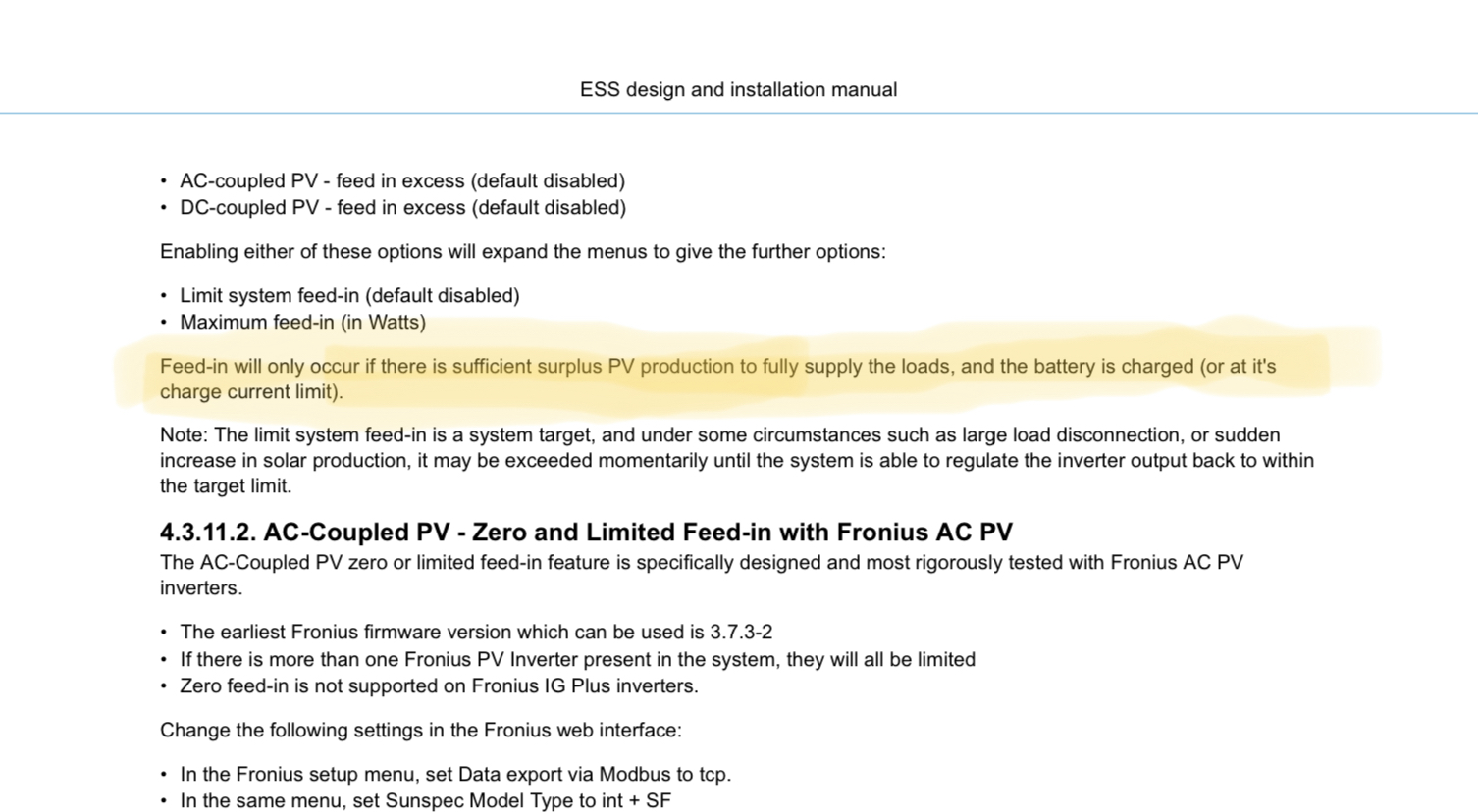
Also read this in the ess manual for CCL.
why do you say that?!
i assume you are either not familier with that situation/setup ( i assume so, because you didn't know that BMS-CCL is ignored)
This would not be unusual, because you wont see any problems with that, if
- battery set is big enough
- Smartsolar MPPT's are smaller than Multi Inverter power
If all your systems are designed like this... (and they should be), then its most likely no issue at all.
But i know there are installations, that have kind of too small batteries, or too big MPPT's. Then it really could be an issue.
Or we are just talking past each other, and you dont know what i actually want to say?
Could it be possible to by nodered to set mppt max charge to i.e. 35A every night, so this will be the max battery PV charge. And when CVL is reached(charged battery), the mppt were set to full charge capacity to feed in max energy?
The issue of "DVCC charge current limits are not applied to DC MPPTs when ESS is enabled with Allow DC MPPT to export. This is to get maximum output from the solar panels for export." has come up many times! Despite it being "in the manual" I personally think that Victron should address the issue since there are cases where clients are "unknowingly" exposing their battery bank to excessive charge current.
Yes... if you size the battery bank and PV panel array correctly then this problem goes away. But, we all know how expensive batteries are and often we try and get away with the "least" number of batteries to get up and running? Never mind the technical complexity, I would say that this is human nature, despite it sometimes being a false economy!
So, for now we are stuck with either disabling DC feed in so that the DVCC CCL is respected, or sizing the battery bank large enough with respect to the MPTT (s) max charge current output and enabling DC feed in excess. There is another option and that would be disabling DC feed in until the battery bank has reached 100% and then switching feed in ON. This gets over that critical point when the batteries are getting above say 90% (just when they want to start throttling back the MPPT), often late morning when the solar irradiation is getting to its highest!! I have found that with my batteries (Pylon) when they are at 100% I can switch to feed in and the charge/discharge current is minimal even though I may be feeding 2kW to grid. But it is a PITA to have to watch it all the time.
In light of this post I have done a simple test of lowering MPPT max charge current (easy to do in Victron Connect) and with my system it does respect this regardless of DC feed in switch position!
Here's an example of a typical "small" system with Multi-2 48V 3000/35/32/GX, 2x MPPT 150/35, 2x Pylon US2000C. So, at max the 2x MPPT could put out 70A which is greater than the 2x Pylon CCL of 50A. By changing the MPPT max charge limit to 25A they will not produce more than 50A...? This appears to be the case (you could lower it further if desired?). Its not a perfect answer... but I believe it does give a limited safety net. With this system it is not restrictive since the inverter is only rated at 2400W continuous anyway so I am not really exporting less than I want to.
I have the same issues - I did a simple Node-RED flow to control DC feed in grid when CCL is <95A or when battery is 90% SoC. But it is walk around but it works - better than nothing. Bad thing is even I would enlarge capacity of battery - I still can not get CCL greater than 100A because in Pylontech Force L1 batteries is 100A limit even if you have 10 or 20kWh of capacity due to connector capacity between battery blocks :( So this would not be my solution. To be honest - I am facing problems with High charge current alarms even when DC feed-in grid is OFF. I have CCL limit 90A in DVCC and still this alarms - but only when sky is quickly changing (clouds / sun / clouds / sun). I am little bit pissed of because I do not know where can be the problem :(
The logic is quite simple:
what converter is used, how many are connected in parallel, series (L1, L2, L3) or series-parallel.
In my case, I have mppt 3x 150/45 + 2x 150/85 = 305A in the peak :) I used to have it as an offgrid solution, but now I had the possibility to connect to the grid (hybrid solution) and send the surpluses out.
I have 1x MP2 5KVA, so it gives max 4kw, 4kw = 80A in DC ok, I will use this energy somehow :D but the remaining 225A system wants to put it in a 14kwh battery, which can be charged with max. 148A, but nobody in their right mind wants to charge 148A :D ... 77A will sit on the bus and when it has nowhere to go, if it probably goes ... to the battery... why, because Victron... :D OK BMS would should have stopped charging. Honestly, no supprise I had 3.65V on the cells (of course not on all of them, that's even worse) :D Should, that's the right word... :D
Why can't the system limit production if it is used e.g. one converter? Why can't the system say that the max. will the charging current be xxxx amperes? Everything above the set limit will be suppressed by mppt and everything below this limit will be controled by CCL from BMS ?
Is Victron really trying to tell me (us) this is a problem that it not to be fixed?
As it was written here for MP, it works for MPPT, doesn't it... :D That's so magic :D
I agree with you. There "should" be a software fix/control for this. It has been an issue for a loooong long time!!
Imagine you have PV panels distributed east 3kwp, south 5kwp, west 4.5,
I probably don't need to describe the scenario of how it ends if you don't turn off the feed-in :D
Because the panels are distributed in this way, they maximize the solar gain even in not good weather. For example when there are only sunny days and I can't help myself at all by reducing their output to MPPT (settin down currnet charge), yes it is also one a solution, but a much more rational solution is to turn off feed-in under ESS and use the grid only as a backup.
So if you want to cover your self-sufficiency in a hybrid system as much as possible, it looks like the Chinese colleagues have overtaken the Europeans :D in this too :D
I'm currently in the same position, that I want to turn on the DC feed in.
In my opinion the DVCC is a critical value, that cant be ignored!
If a single cell is peaking, that voltage is skyrocketing and my BMS is triggering the main shunt-trip and everything is gowing down.
Setup:
3x MPII 48/5k
13kWp at 2x 450/100
42kWh LFP with Batrium
The rule to get maximum feedin would be simple in my mind:
The Multis must convert following Power to limit the charging power
Ampere Multis = Amps Solar - CCL from BMS
If the Amps for the multis is calculatet to be negative, set the amps to 0
Sadly I seem to have the same issue.
For now I have disabled feed-in until I get some time to look into this probably with an Node-Red solution as @Pedaaa suggested -_- but I am also annoyed about this
That's the thing you dont have to get fancy with node red...
Reducing either your programmed charge voltage (as in a pylontec system which asks 53v but system programmed at 52/1v)
This allows feedback without overvoltage or voltage overshoot. To change direction of flow (and create feed in) there has to be a higher potential somewhere.
Over Amps is a different story. If your mppt battery ratio is off there is not much to do there except limit feed in maybe. (It depends on the battery.)
If your batteries are not great at balancing with higher charge amp (cell overshoot) then maybe beef up the active balancing. Problem solved.
If the system followed the ccl and the battery sends 0A then no feed in happens, that request has to be ignored for the other request of feed in to be fulfilled.
Hej @Alexandra, thanks for the input.
The issue I was investigating today when the sun was out is actually that the CCL reqested something around 17-25A (for testing purposes) but it was receiving way more - according to the sun on the Panels and what the MPPTrackers outputted. I set the BMS to switch off at 40A Charging Current, which it did.
Non the less it was simultaniously inverted everything the House asked for or maybe it was an coincidence but at least this was what I was observing. So if that was the case than I dont understand why it could not invert more so that the CCL was matched.
So according to your suggestions this would be the second case over-amp and solvable by limiting the feed in(I guess into the battery) which in my opinion should be also solvable by setting as sugested above the "gridfeed in power" (not sure how the correct terminology is here)
Non the less I will try to investigate and see if I can incorporate the Voltage sinks on the DC rails into my thinking.
Shouldn't it be possible to (programmatically) use the grid-set point to design some sort of "loading-limit" while feed-in is enabled?
I.e. if the MPPTs producing 100A instead of the desired 70A, set the grid-set point to -1600, so the Inverters are pulling out 30As of the "DC-Pool"?
Doesn't avoid peaks hitting the battery when solar changes, but Peaks shouldn't hurt batteries. My EVs battery is going from -80kW to +80kW depending on the throttle.
At least that could / should avoid a permanent charge beyond what you want for your battery.
If someone could manually test if using a negative grid-set point to control grid-feed would work out, I could write a script for that in about no time. Will then need it in the not to distant future anyway ;)
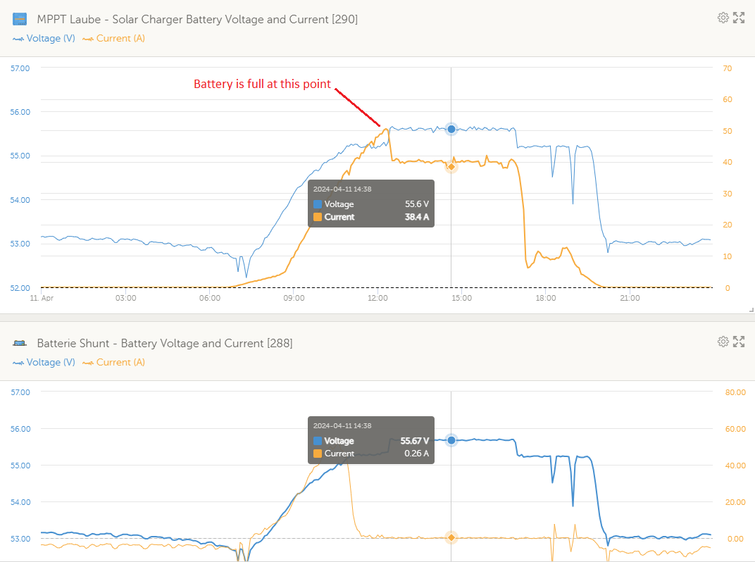
I tried a few times the DC excess feed in, and also observed the DC voltage to rise above the set limit. But after some analysis the situation became clear.
If the battery is full, the MPPT is throttled down to a value the Multiplus can convert into AC. I observed this very clear. So no load/current is going to the battery.
But to be able to output any energy of of the MPPT, the DC voltage between the MPPT and the busbar/DC-rail, has to rise at least a little bit, otherwise no current can flow. @Alexandra told you this already. Just imagine, no voltage difference, no current flow!
That's why the voltage at the Busbar is rising and unfortunately also the battery's voltage is rising and causing a un-wanted voltage rise. In my case this is rising from 55,2V to about 55,65V. The current into the battery is almost 0A.
So the system is behaving absolut correctly, it just has to somehow deal with the physics. ;)
Attached two pictures showing how this looks like in my system with one 150/75 and one MP2 48/3000. As the peak is reached, the battery is full and only the excess is feed in. The MPPT produces only the amout the MP2 can take. With the effect described above.
Yes, iirc it raises by up to 0.3V much like keep batteries charged does.
CCL works fine, after the initial wobble after it turns on.
Common misinterpretation that DVCC ignores CCL from the battery, it doesn't. It ignores manual overrides the user has set in DVCC. Two different things.
Not to what I have seen.
If I set the CCL to 10A in the DVCC settings while DC-PV feed-in is active and the batteries are being charged, it ignores the CCL settings and pushes everything coming from the MPPT to the batteries.
So yes, while batteries are charged from DC-PV and feed-in is active the CCL settings are ignored from the VenusOS/ESS/MP2 (which ever system actually limits the charge current).
But I guess this is apparently intended behavior, or rather documented.
The manual override - the bit you are setting - is ignored. Expected and documented. The actual CCL sent by the BMS - visible via the GX or advanced widget - should be honoured.
In most cases people are trying to manually lower the charge level below the CCL sent by the battery. This won't work.
I should mention, that I use a smart BMS that is also controlling the CCL. So I don't know if DVCC is working or not as the BMS might be the one controlling the current here... Definitely there is something different in our setups or configurations to show this different behaviour...
@Velociraptor85
It seems what the system ignores is your 10A set in DVCC but not the CCL requested by the battery? The two figures are different.
F.
OK so I tested it
* disabled the DVCC defined CCL of 10A
* set lower levels for the CCL(max 20A) which is reported by the BMS by changing the values in the dbus-serialbattery config and reinstalling the "dbus-plugin"
For me, it was again the same behavior as before:
* if DC-PV Feedin is disabled, it honors the set CCL values by the BMS-system (dbus-serialbattery)
* when enabling DC-PV Feedin the CCL values set by the BMS are ignored and more than the defined Current is used (all the PV system has to offer)

My current workaround is that I have wrote a small node-red block, changing the Feed-In to disable when the battery is charging and enable when it's full.
Nonetheless, I would be happy if the system would work as implicitly expected ^^
@Velociraptor85
What you are saying is contradicting what @nickdb is saying. According to him, CCL from the BMS is never ignored. I haven't experimented so I don't know who is right.
According to your screenshot, the BMS is asking for 14.07A as CCL. What is the MPPT supplying to the battery at that point with feed-in enabled and with feed-in disabled?
F.
We are still talking about excess DC feed in, right? Because the picture above is showing a situation where the battery is not full yet. Or you just want to show, that CCL is beeing ignored?
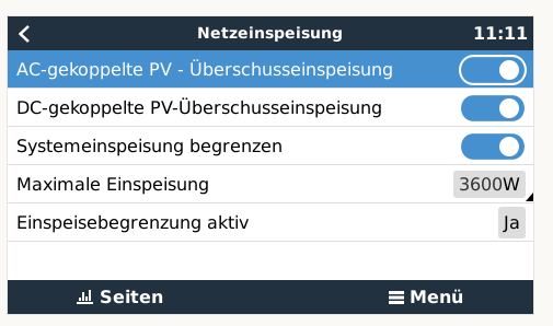
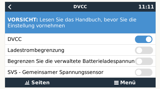
And I see, that your DVCC "Ladestrombegrenzung" is not activated. Please activate this and also select in the DVCC Menu the following:
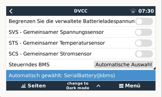
I have set the DVCC CCL to a max of 75A in total. In parallel the BMS delivers the same limit until the battery gets full, then depending on the cell voltages the charge current is more and more reduced down to 0A. This is configured in the dbus-serialbattery config file.