question

Paul B avatar image
Paul B asked

Multiplus II 48/5000 showing Incorrect DC Battery Voltage reading

Hi I have just removed a Mutliplus 48/5000 from and site a Upgraded/installed a Multiplus II 48/5000

The latest firmware has been installed 459

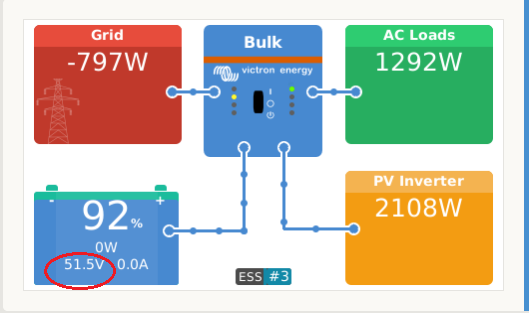
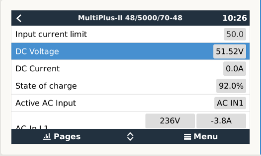
The CCGX is displaying a resting voltage of 51.5

my two volt meters plus the BMS show the voltage as 53.5

it seems the Multiplus II has a incorrect voltage reading and is showing a way to low a reading

Note Charging has been turned OFF by the VE-BMS as I charge these to 3.5 volts per cell then let them drop to 80% SOC before charging is turned on again

is there a calibration available to adjust this anywhere ?????

I have tested the voltage AT the Multiplus II terminals 53.5 and the batteries themselves also 53.5


The Old multiplus 48/5000 voltage readings we all correct

assistants and other info

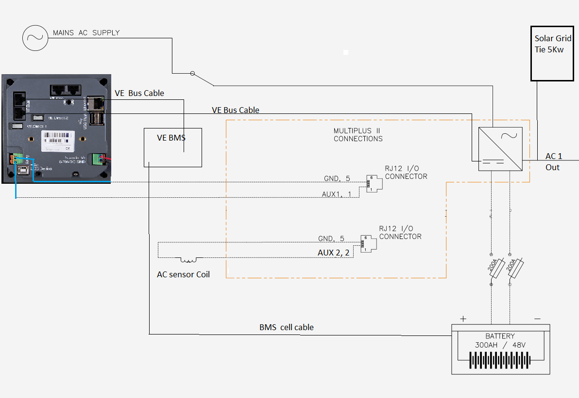
Gen flag is used set ignore AC1

AC sensor installed

ESS is installed with Grid Tie Inverter 5Kw

Relay on

Relay off

Panels installed are 4.5 KW

only AC coupled

Battery bank 20Kw Lithium Phosphate


Any suggestions


Multiplus-II
1557631561975.png (39.8 KiB)
1557631604576.png (37.9 KiB)
2 comments
2 |3000

Up to 8 attachments (including images) can be used with a maximum of 190.8 MiB each and 286.6 MiB total.

boekel avatar image boekel ♦ commented ·

Hi Paul,

Maybe best to contact your distributor if everything else checks out ok (quick test with standard settings and no assistants first?)

0 Likes 0 ·
Paul B avatar image Paul B boekel ♦ commented ·

Just did all that removed the assistants and the under voltage was still the same

my main worry is for overcharging but it seems to read the voltage correctly when charging its only on idle or discharging at any level that its reading low

Anyway the BMS will turn it off if a overcharge occurs

Its nice to have a secound line of defense with the BMS low and High for that matter.

I have sent it off to my Victron local area manager so its in there hands now.


0 Likes 0 ·
2 Answers
Paul B avatar image
Paul B answered ·

Problem Isolated I think

Ok its now 7pm time to do some more testing and voltage is still lower than it should be on the DC battery voltage (see below )


Now if I UNPLUG the RJ12 cable on the PM2 then the solar goes to 7000 odd watts now I understand this as the Aux 2 is now O/C and also the mains disconnects as the Aux 1 is also O/C thus the mains goes off also all hoiw it should be


But interestingly is the DC voltage goes up back to where it should be as well hmmm


The voltage on Aux 1 and Aux 2 is 4.91 volts pin 1 to pin 5 when O/C Aux 2 has a voltage of 113mv pin 2 to pin 5 and 4.91 when O/C or the ac sensor removed

If I check when the RJ12 is plugged in then its 0.00 on Aux 1


Pin 1 is Aux 1 high

Pin 2 is Aux 2 high

Pin 5 is Common Ground/Low when the Aux 1 relay is closed pin 1 is shorted to pin 5 and also Aux 2 ac sensor coil is connected pin 5 and pin 2


Now when I remove the Assistant General flag so that the AC in stays on when powering up (that’s used to ignor ac on AC1) (still all others still the same)

When I remove the Closed loop provided by the Venus as the output relay is closed thus it was turning on the Gen flag using Aux 1 and thus sending the Aux 1 port LOW and thus reducing the voltage across AUX1 to ground to zero ie High or low


The problem with the Low voltage reading stopped occurring when it was High and reoccurred when it was low or put the loop back on and the DC battery voltage reading dropped


However on AUX 2 which has the Solar on it is still reading 75w, the AC sensor is correctly set for 5Kw as per the instructions


Awaiting further info from Victron


Unless anyone can see something I am missing


1557751786073.png (39.8 KiB)
2 |3000

Up to 8 attachments (including images) can be used with a maximum of 190.8 MiB each and 286.6 MiB total.

Paul B avatar image
Paul B answered ·

Re the below Schematic in the MP2 Manual,

when using Aux 1 and Aux 2 the drawing mentions a 10K ohm resistor does this then mean that the two rectangles circiled in blue are 10K resistors ??? or are they loads

and does this mean that if I am using these as a Aux Swicth that they need to be inserted in the circuit

inc the AC Sensor as well thats connected to AUX2 ????

looks like it maybe the case but just wondering if anyone can confirm this

Current configuration


1557804138057.png (48.9 KiB)
1557811083599.png (152.0 KiB)
2 comments
2 |3000

Up to 8 attachments (including images) can be used with a maximum of 190.8 MiB each and 286.6 MiB total.

boekel avatar image boekel ♦ commented ·

That diagram is the internal logic, the resistors are 'pull up' resistors so you can pull to ground to easily drive the inputl

0 Likes 0 ·
Paul B avatar image Paul B boekel ♦ commented ·

yes I understand that but when you pull to ground thats when the DC battery voltage becomes incorrect.

so its something to do with that circuit

on that version of the MP2


Any way I am using the Gen Flag to ignor ac in and using aux 1 to turn it on and off

AUX 2 is being used for the ac Current sensor as well


do you know of any way t turn the gen flag on and off without using aux 1 and that would also solve my issue as well,


I was more checking to make sure that I did have to add the 10K resistor but I have been told that its all internal

0 Likes 0 ·