question

Dylan Tucker avatar image
Dylan Tucker asked

Another schematic review

campervan-schematic.jpg

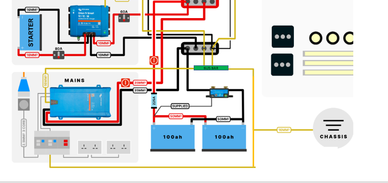
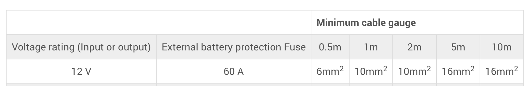
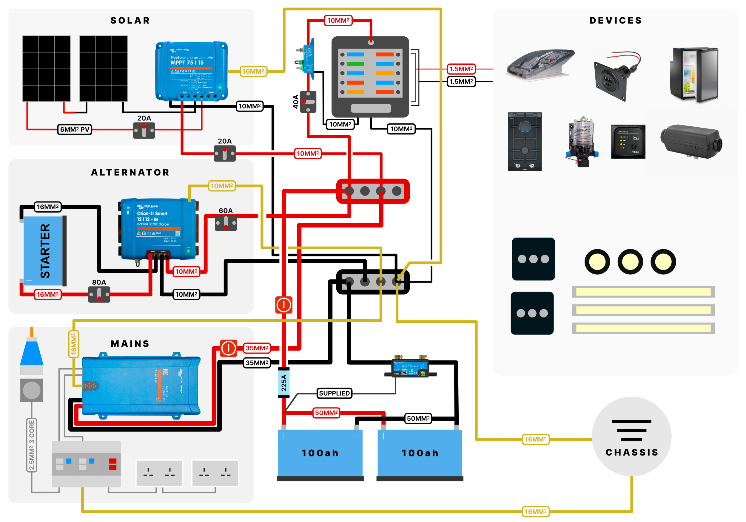
Hi everyone - was hoping some kind folks could do me a massive favour and look over my campervan schematic. I've been a bit confused about wire gauges and fuses in particular, but between consulting other schematics and the Victron manuals have come up with this. In general all cable runs are short as everything is super compact in the one under-bed cabinet, excluding the starter battery to B2B charger run which is approx 2.5m. So perhaps the cable gauges are over the the top here, but it's a starting point. (This is my first time doing anything like this so please bear that in mind!)

One question I do have here is do I need to run both positive and negative cables from starter battery to B2B or can I just run the negative from the chassis into the B2B? This would help my cable run be easier/neater from the cabin to the load bay.

Thank you so much (and a happy new year!)

schematics
2 comments
2 |3000

Up to 8 attachments (including images) can be used with a maximum of 190.8 MiB each and 286.6 MiB total.

l81ker avatar image l81ker commented ·

Hi Dylan, my opinion is that keeping the negative cables and not just relying on the chassis as a conductor is very wise. A bad/corroded ground connection to chassis can cause some serious problems. Keep them, it's worth the effort.


On a different and related point, I see your AC bonding is kind of 'here and there'. I strongly advise that you ensure all the AC bonding goes to a single common point, rather than as you have it. Consider taking the same approach to the DC negatives, i.e. avoid ground loops.

See e.g. Wikipedia as reference if you'd like to understand more on this.

https://en.wikipedia.org/wiki/Ground_loop_(electricity)


0 Likes 0 ·
l81ker avatar image l81ker l81ker commented ·

here is a very quick example of how you might consider changing it, by simply adding a busbar as the common point (I didn't change all your wiring, just a few to give the example).


1672495784177.png

0 Likes 0 ·
1672495784177.png (92.6 KiB)
2 Answers
jkmann avatar image
jkmann answered ·

Just a few points:

1) yes, you can use the chassis ground for the Orion TR supply (-) return to the battery. You should use the non-isolated version of the Orion TR if it's available in the size you want. Double check the fuse specification as well. Is 80A correct on the input?

2) the solar, ideally, should have a double breaker on input. This is because the solar (+) can short to the van body without tripping your breaker if you have isolated the solar MPPT controller. This would be required to meet ABYC standards on a boat. However, many people do it the way that you have shown.

3) the cable between the (+) busbar and the inverter/charger needs a fuse or breaker.

4) fuses are more reliable and typically have lower resistance than a breaker. So, unless you need the switching function, prefer a fuse over a breaker.

You don't mention what kind of batteries you are using. You need some kind of BMS in this system. If you use Victron Lithium Batteries you can connect everything with a VE Bus BMS to control the allowed to charge and allowed to discharge conditions. If you are using batteries with an integrated BMS that's also OK, but you are wasting some of the intelligence of the Victron components.

3 comments
2 |3000

Up to 8 attachments (including images) can be used with a maximum of 190.8 MiB each and 286.6 MiB total.

Dylan Tucker avatar image Dylan Tucker commented ·

Thanks so much for your reply. Responses below:


1) I've already bought this and it's just called the 'SmartSolar MPPT 75/10' - I have no idea how to find if it's isolated version or not or this was even a thing. Is there an easy way to find out and what exactly is 'non-isolated' about it? I can't find anything on Google on this one and the only mention on victron is in the manuals section where only 'isolated' is shown as an option.

The 60A fuse is based on a few schematics I've seen but also this from the manual; have I interpreted this incorrectly?

screenshot-2022-12-31-at-201425.png


2) Thanks I'm only just reading about double breakers now and will continue researching; a new one on me and shows me how much I'm yet to learn.


3) Regarding fuse between busbar and multiplus, the manual just states there's an internal fuse and has no recommendations for an external. Do you know what would be required for a 12|500 multiplus?

4) Ok thanks - I'll revisit this aspect. Perhaps it would work out better if I just used a lynx distributor. I had read that the place this is most a problem is where i've included fuse. I would like to be able to isolate the solar panels so would you keep the breakers here or add switches and fuses?

Batteries: I'm using AGM; I'm not entirely sure what you mean about battery management, but I have the battery protect and smart shunt and had read that I don't need the Battery Balancer as this would be done on it's own.


0 Likes 0 ·
kevgermany avatar image kevgermany ♦♦ Dylan Tucker commented ·
Isolated is mostly used on Orions, means that the negatives are not joined across input/output or to the case.

For most applications the non isolated is fine That appears to be the case here.

Fuses are to protect cables. Size for cable carrying capacity, or smaller if you know the current will always be a lot lower. One in the positive close to the battery and as you have charging, it won't do any harm to add one close to the multiplus, but not necessary at all as per manual. It adds nothing but complexity. The internal fuse is straightforward to change. But if it does blow, find out why.

On the PV breakers, best to get an isolator switch that cut both positive and negative. That way you can completely isolate the panels. Ideally they will have standard MC4 connectors, so you won't mix positive and negative up when making connections. This van go where it's convenient. You can get inline fuses with mc4 connectors on each end for the panels. One on the positive close to the output panel is sufficient, but you can put one on each panel positive if you wish.

Battery Management systems are needed for lithium batteries. Not used on AGM.

Battery balancer will equalise the voltage between two batteries in series, e.g. two twelve volt batteries connected to give 24V.


0 Likes 0 ·
jkmann avatar image jkmann Dylan Tucker commented ·
The Victron SmartSolar MPPT's do not isolate the battery (-) from the solar (-) internally, so the fault danger is relatively low when using the Victron MPPT equipment. However, you should just be aware that the solar (-) is not the same as your chassis ground or battery (-) unless you proactively tie them together or use a device to accomplish that. It's still a good practice to use a double breaker so you can isolate the solar fully, but I think this falls into an optional rather than essential practice since I've seem so many people not do it.


For the Orion TR, I would drop down from the 80A that you show on the input side to the 60A per the manual. Definitely use a breaker rather than a fuse for the input so you can mechanically isolate the Orion TR when doing any maintenance. You can use a fuse on the output side (I would).

It's normal and safe practice to protect all cables from fault conditions by putting a fuse between the battery and the consuming device, normally as close to the battery as possible. However, if your Multiplus has a fuse in it that protects the cable (mine does not), and that fuse is designed to protect the cable from over amperage, and the cable is short enough (ideally 18" or less) from the busbar to the Multiplus, and the fuse is reasonably accessible, you can get away with not putting in a fuse.

Make sure that your cable is big enough to blow the Multiplus fuse without overheating. You can follow the manual on that. In the case of my Multiplus, the manual specifically says that your wiring and external fuse needs to be able to handle a hard fault to ground of the (+) cable ... but your model might not require that. In any case, during a fender bender if your cable to the Multiplus gets compromised before the fuse, and you did not separately fuse it, you can have an electrical fire. So ... just think twice about it before you decide.

ALL of my cables are protected by breakers or fuses near the power source, and that is considered standard practice for any cable longer than 18". People can often get confused about where to place the fuse or breaker. For both inputs and outputs to the battery, your fuses should be close to the battery. Why on the battery inputs? Because if the cable is compromised, the batteries have MUCH more amperage to start a fire with than the source device, which is fused on the input side anyway.

As @kevgermany mentioned, AGM batteries don't require a BMS. But, since this is van I would expect that you are planning to use Lithium Batteries. Of course, not everyone does. If you use the VE Bus BMS it will integrate well with the other devices.

Also, although a DIY system is interesting, you could also use a pre-built system from Goal Zero, for example, for the size system you have designed.

0 Likes 0 ·
Kevin Windrem avatar image
Kevin Windrem answered ·

One general comment: the WIRE needs overcurrent protection. In most DC systems, a source such as a solar charger or the B2B charger will limit their output current. A wire short will cause unlimited current from the battery so fuse/circuit breaker should be located near the DC distribution

3 comments
2 |3000

Up to 8 attachments (including images) can be used with a maximum of 190.8 MiB each and 286.6 MiB total.

Dylan Tucker avatar image Dylan Tucker commented ·
Thanks - so I have a breaker near the 12v DC distribution fuse box but apart from that I'm a bit lost what I should be doing as per your comment; do you mind helping educate me a bit? Thanks so much for patience
0 Likes 0 ·
Kevin Windrem avatar image Kevin Windrem Dylan Tucker commented ·

The breakers for your distribution, solar and B2B (Orion) should go close to the battery (busbar), not at the device. As I explained above, a short in one of these wires to chassis would cause large current flow. If the battery fuse didn't blow due to wire resistances, the wires would burn up.

Chassis connections should be large enough to trip any breakers (or blow fuses) due to any short to chassis because that's the path of the fault current back to the battery negative.

jkmann, comment about isolated vs non-isolated was in reference to the Orion between your starter battery and the house battery, not the MPPT. In the case of the Orion, the starter battery negative is connected to the chassis, so if you use the non-isolated version of the Orion, the negative connection from the starter battery essentially becomes THE chassis connection for everything in your system. With the isolated version, you can define your own "ground". You show an isolated version in your drawing (4 wires). Non-isolated models have a common negative connection (3 wires).

By the questions you are asking, I get the feeling that you really do not understand all the issues regarding the design and installation of a system such as this. Errors can present a safety issue so I recommend finding someone in your area that is familiar with combined AC and DC systems and Victron equipment.

A good source of information if you continue to DIY is the Victron Wiring Unlimited guide:

https://www.victronenergy.com/upload/documents/Wiring-Unlimited-EN.pdf

0 Likes 0 ·
Dylan Tucker avatar image Dylan Tucker Kevin Windrem commented ·
Ah thanks that makes more sense now; the diagram isn’t to scale in terms of fuse locations, I’ve just grouped them to be more logical for my mind and so the middle isn’t overcrowded. but it has got me thinking that a lynx distributor might be a good bet. Thanks for the link too very handy
0 Likes 0 ·

Related Resources

Additional resources still need to be added for this topic