question

rata1 avatar image
rata1 asked

What is the correct current sense configuration for a parallel pair of MP2's

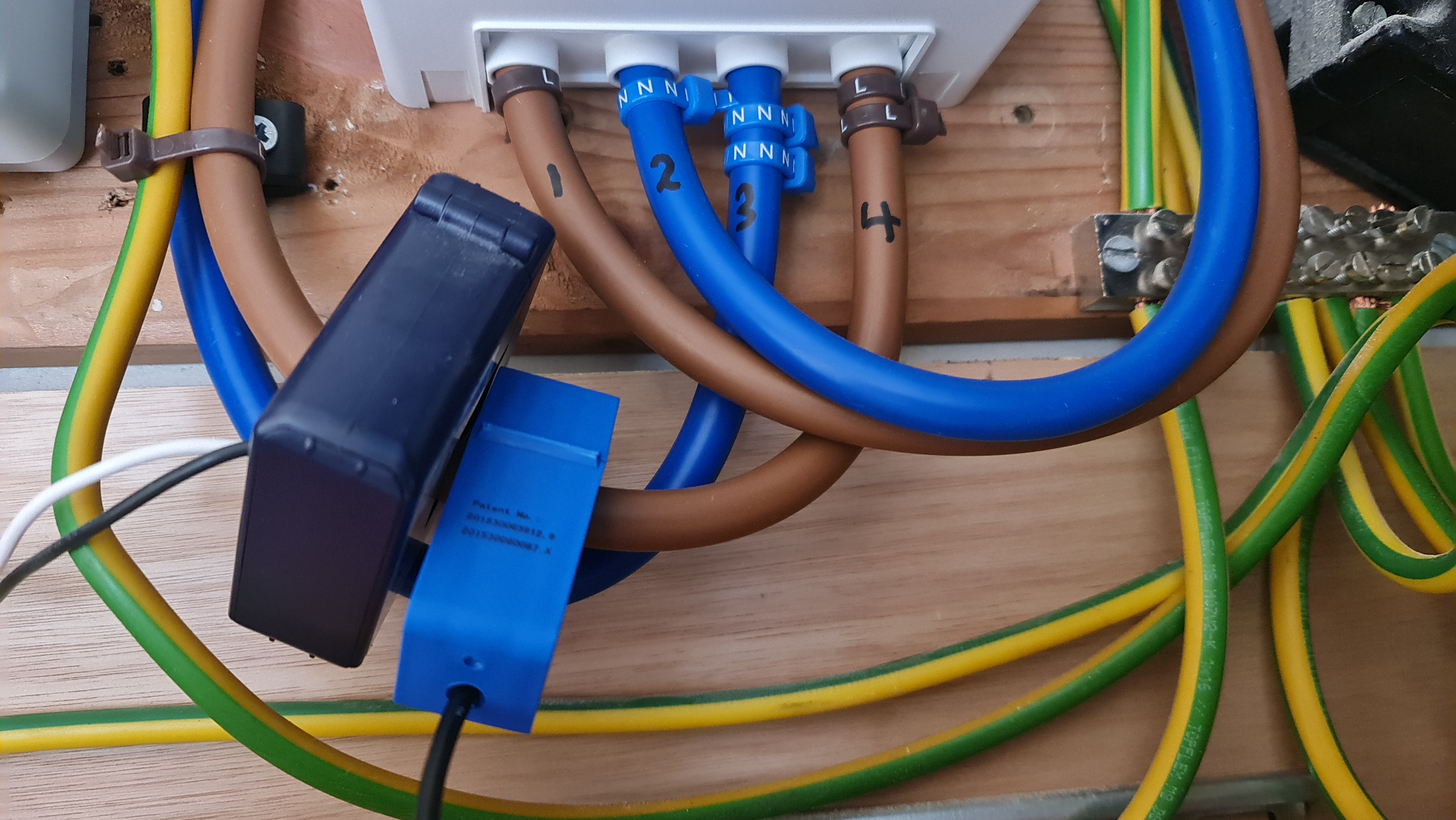
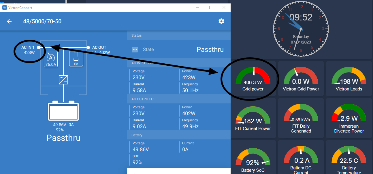
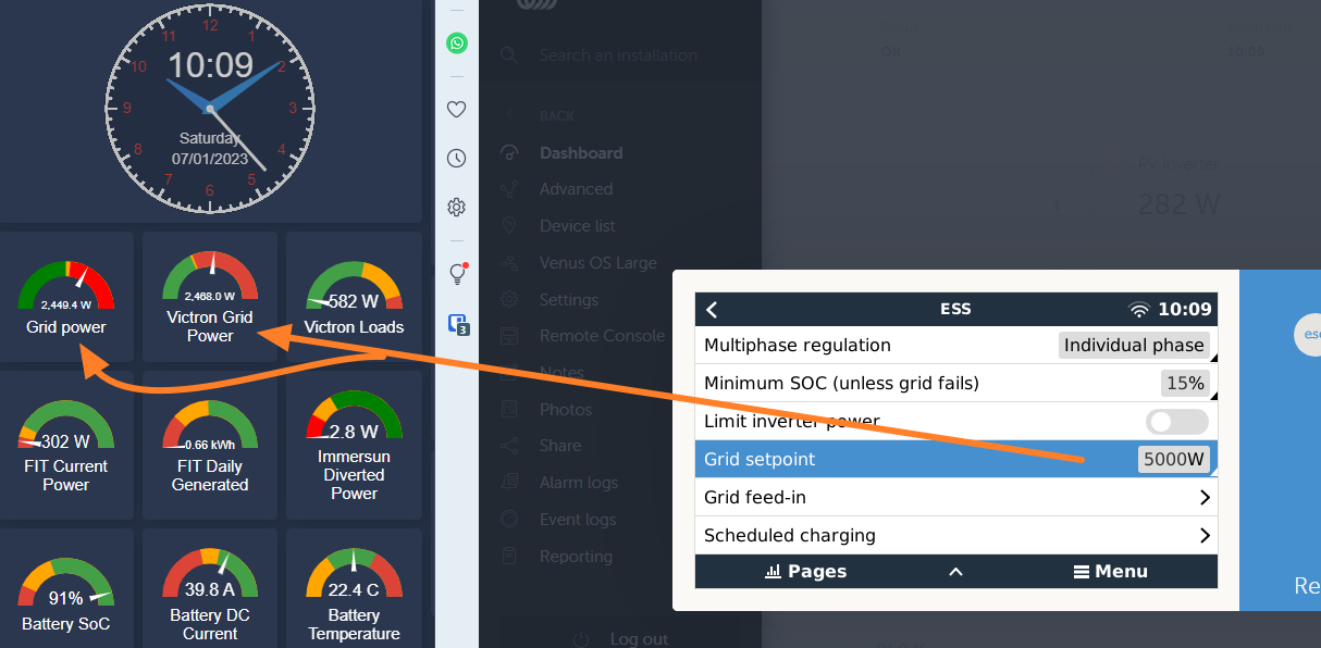
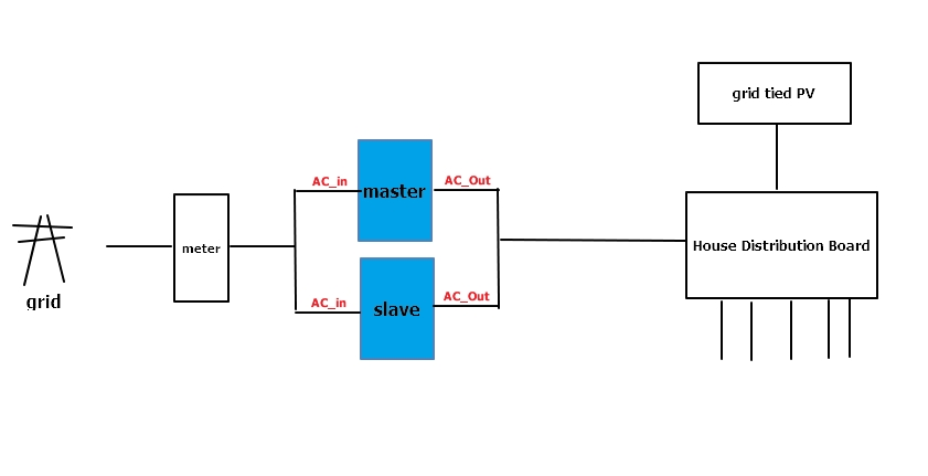
I have a system like below configured as ESS and I assume it uses the "internal current sense" of each to figure out the grid set point.

image-2022-12-23-130503809.png
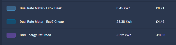
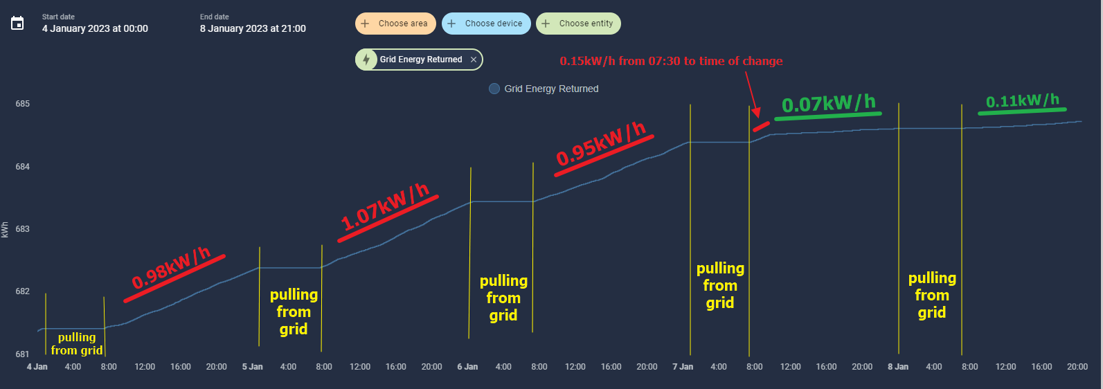
Problem I have is that I export almost 1 kW/h from batteries a day (which is only 17hrs as I don't discharge between 00:30 and 07:30) which is verified by the meter and a separate ShellyEM clamp on the grid.

It seems to me that as it is a parallel system, the slave is telling the master what its current sense is and the master works it out and tries to get to the set-point.

This isn't working well and I read on here that a little give and take is OK, but my take is about 60W/h compared to 0.9kW/h given back.

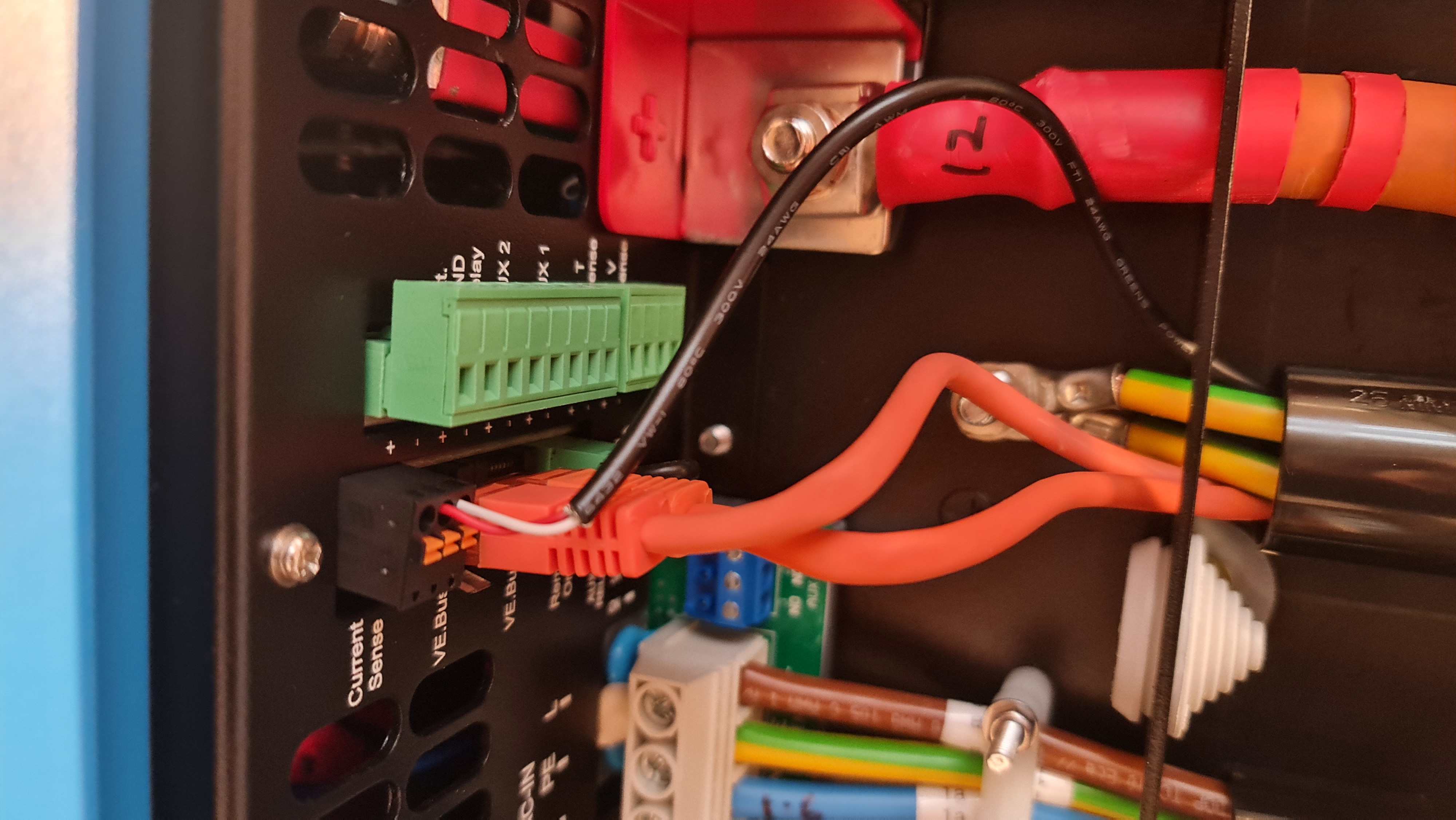
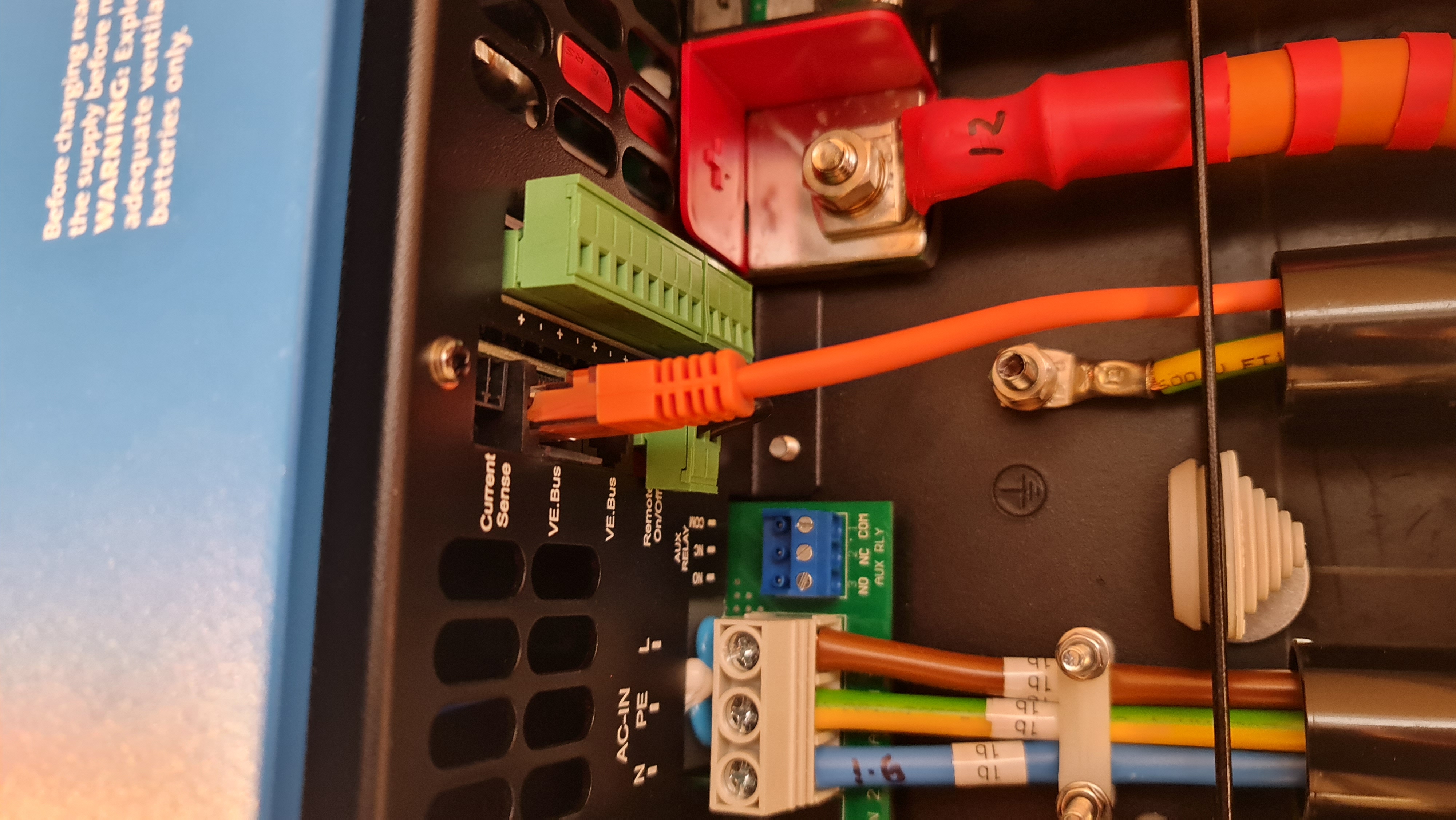
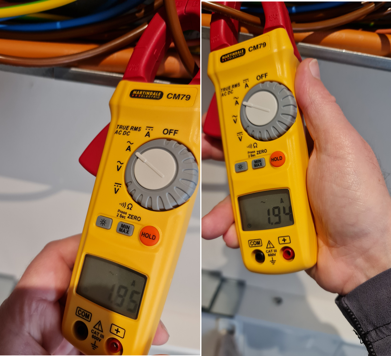
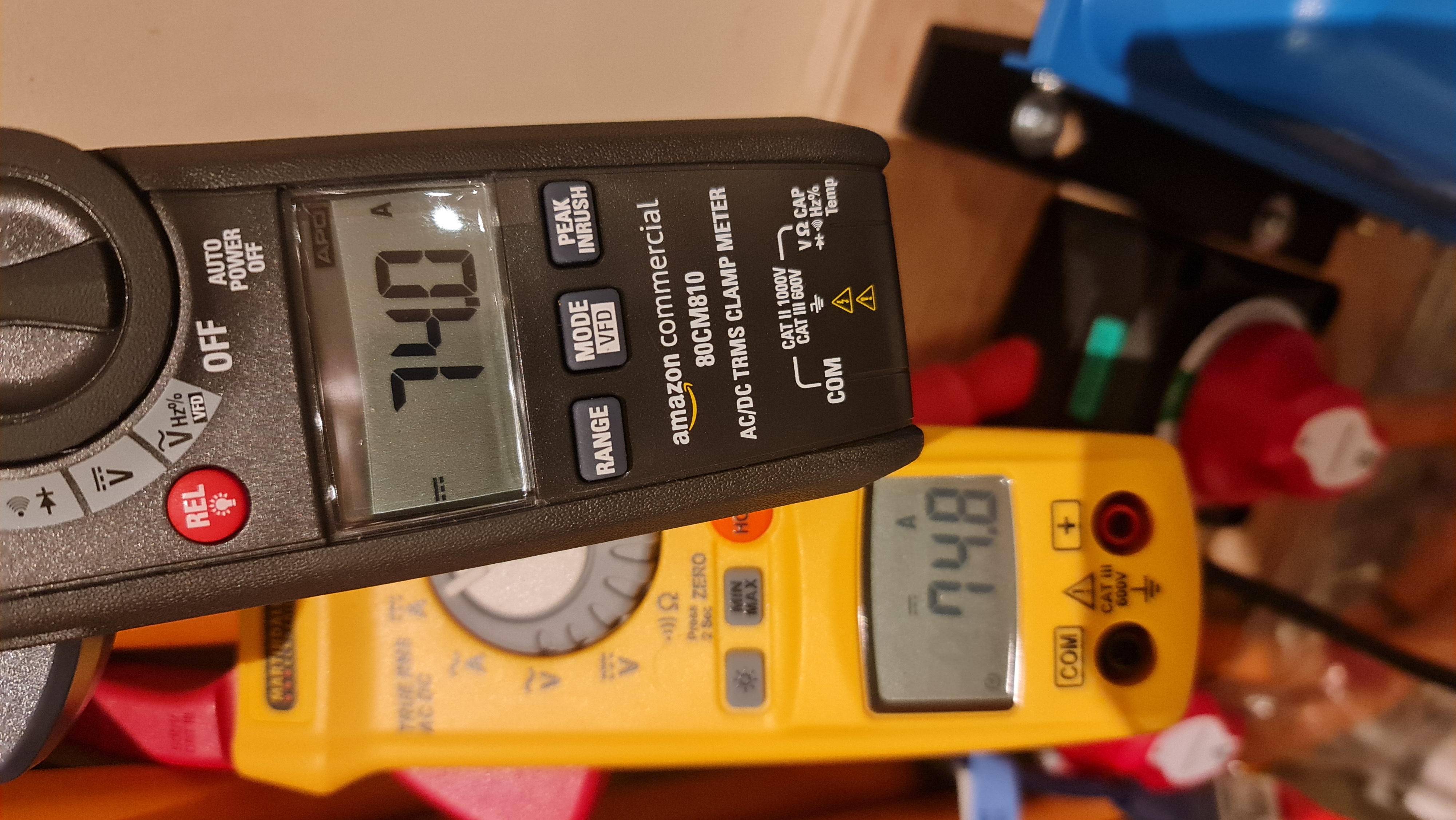
So I got a CT clamp and clamped it on the grid as this seemed logical when connected to the master.

1673278137831.png

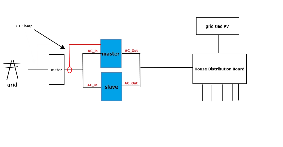
This did the job and prevented discharge beyond the set-point and I was seeing a better in/out balance - so I congratulated myself on another job well done :)

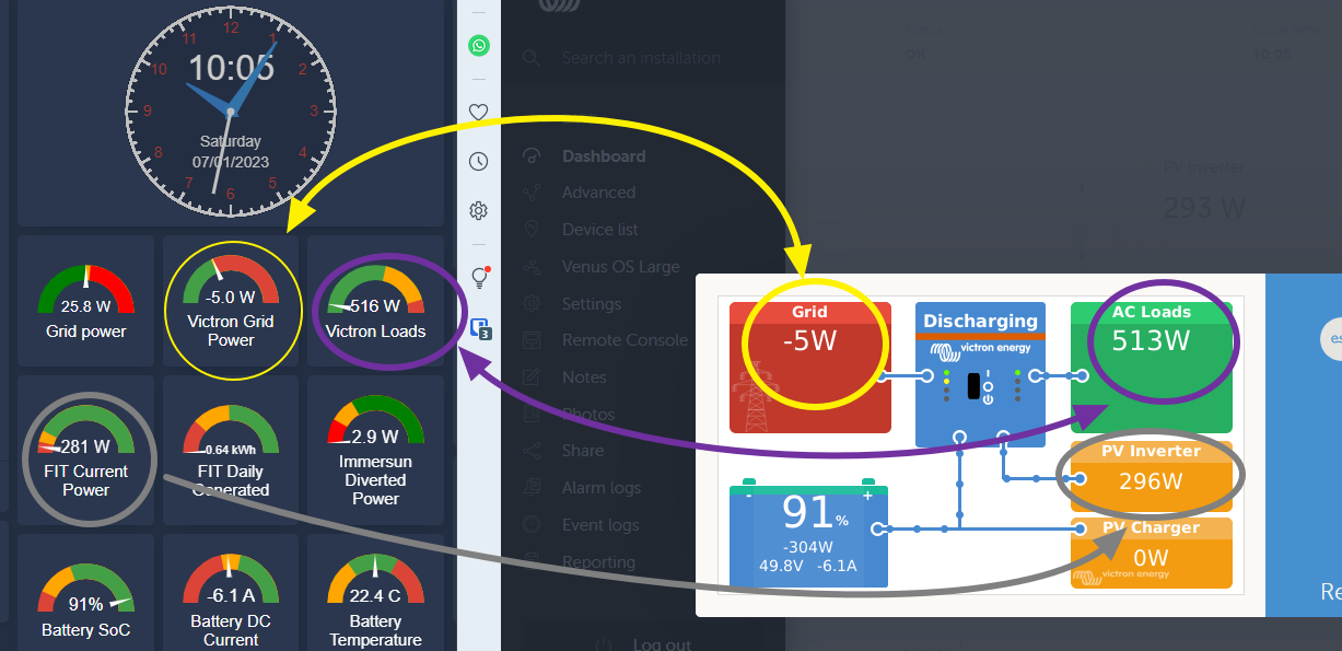
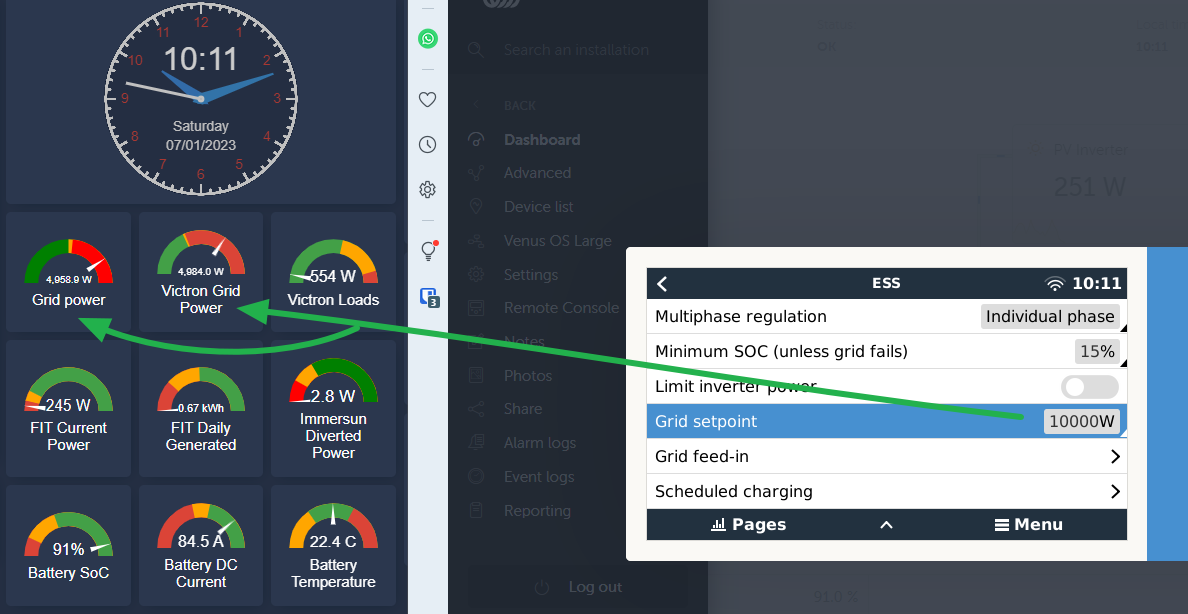
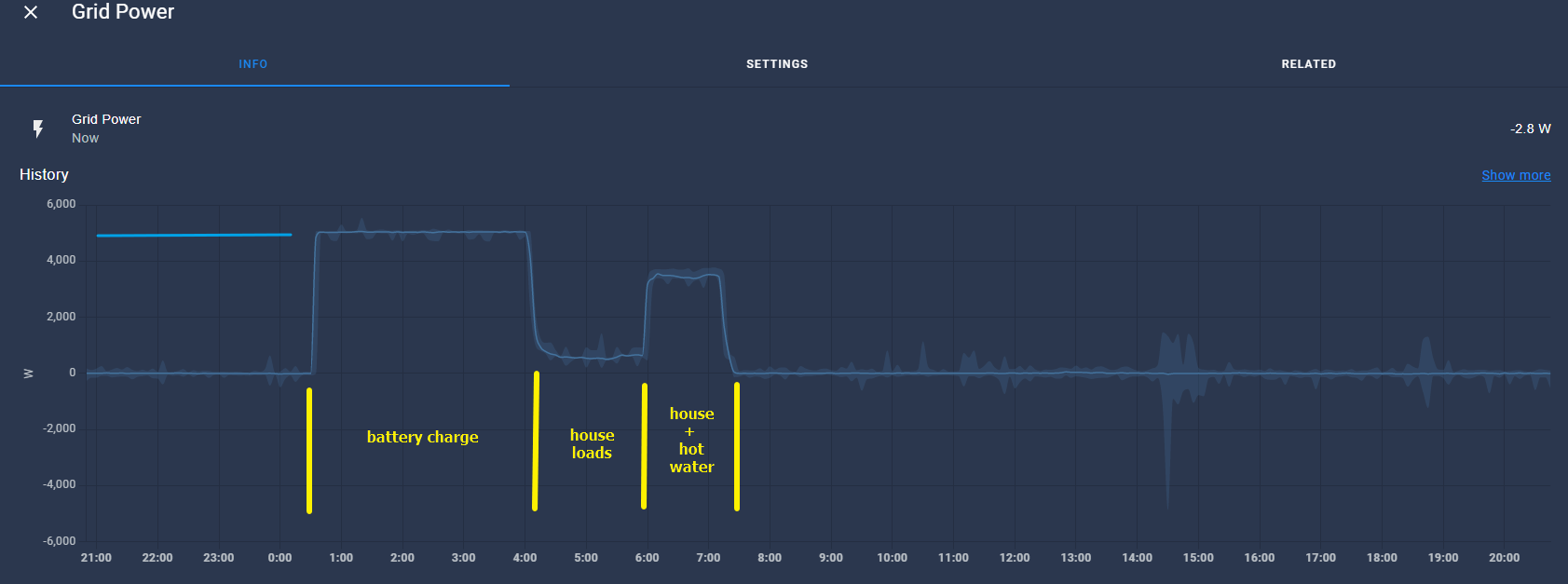
However, when I charged that night (on off-peak) I woke to find the batteries at only 80%. I looked in Home Assistant and saw that despite me changing the set-point to 5.5kW on the Gerbo (by MQTT) I only pulled half of that meaning the batteries couldn't charge in the 7hr window like they normally do

I did a force charge in the day and discovered that whatever I set the positive grid set-point to (in order to force a pull from the grid) approximately half went into the batteries and the other half showed up as a load on AC_out which was completely wrong!

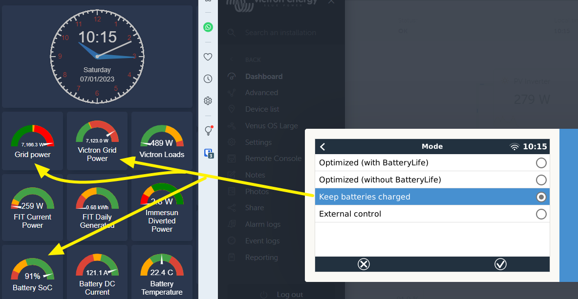
Obviously this is not right so I removed the clamp and all back to how it was.

So my questions are;

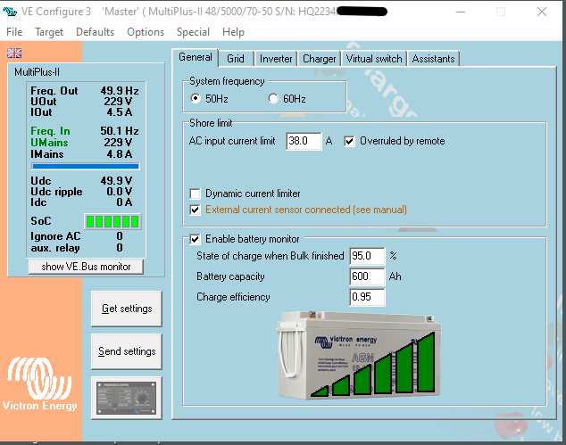
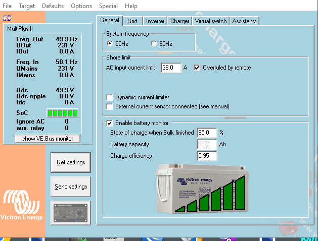
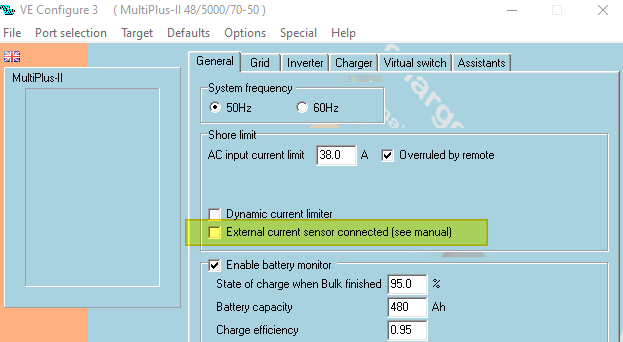
i) when deploying a parallel pair set up like this is it best to use an external CT clamp rather that the MP2's internal CT's and if so - do I need to set "external current sensor connected" in VE Configure 3 AND keep the grid metering in ESS as inverter/charger?

image-2022-12-23-133609753.png

ii) if I don't use a CT clamp and continue to use the internal CTs of the MP2's how quickly does it update and is it via the Cerbo or directly over the VE Bus? If the latter, why is it way out?


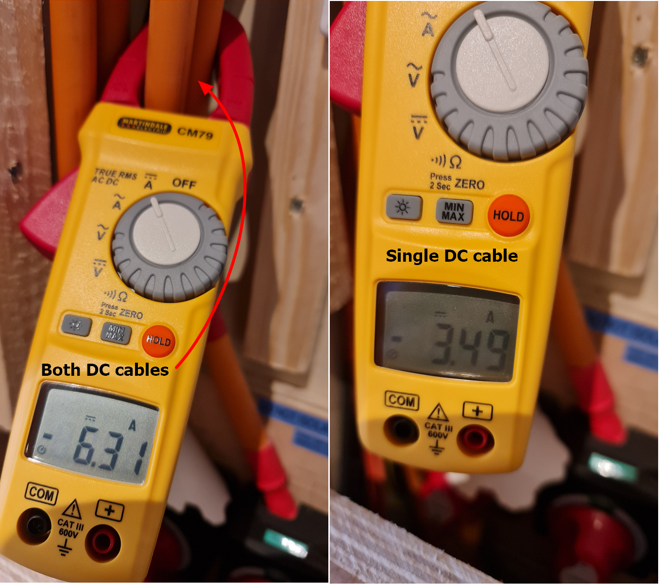
Both the MPs are 8 weeks apart in manufacturing date and balanced etc. They are both the later HW revisions. >HQ2223 at 498

Cheers.

Multiplus-II
2 |3000

Up to 8 attachments (including images) can be used with a maximum of 190.8 MiB each and 286.6 MiB total.

5 Answers
rata1 avatar image
rata1 answered ·

Well I was a bit bored over Christmas so I changed the VEConfigure setting on the master to "external current sensor" and clamped it on the meter live cable. The resulting grid draw was not correct.

Rounding the numbers to illustrate the issue after the change my house loads were 500W and in passthrough on VictronConnect I could see 750W from the grid and the same (less losses) as the load. So seeing 500W but reporting it as 500W plus 250W (which is the half the slave is using).

So I removed the CT connector from the slave (I have the new type not the jack) and the load was 500W both sides. So the same behaviour as before (original post) but I thought I'd give it a try.

I connected the Cerbo back up and tested in the day. Gave back a tiny amount.

Trouble is that when I charged from the grid in off-peak that night by setting the grid setpoint to 5000W as usual, the house load was reporting correctly but the grid import was only 2500W! So even without a connected CT (internal or external ) the calculated power is wrong.

So what exactly is the correct and expected result with a CT clamp on a parallel pair? I would have thought as they were behaving as one unit it was only the master that needed to see the grid and work out what the slave saw, or was assumed to take - i.e. half.

Is this a bug?

If anyone has it set up like this and working could you share please?

It is back to the internal CT's and I am bleeding back 100s of Watts but consuming 10's again.

I reverted because I charge at night and being asleep not sure which unit is doing the work. I assume it is the pair but concerned it may overload. Also the calculated values are all messed up - it is either telling me the AC_out is actual + half the grid import or tells me the AC_out is correct but only consumes half what I tell it to.

With the slave CT connector removed (i.e. open cct), the external CT connected to the grid at point of ingress via the master "EXT CT" and configured as external CT in VEConfigure on the master only I did the following - doubled the grid import value in set point to 10kw (from 5kw) and indeed the load on AC_out remained the same around 500W and the the import from grid was 5kw. The batteries charged as expected - i.e. double the charge current from a 2.5kW pull if set point was 5kW.

I could leave this like this as likely both inverters are sharing the load of about 80A (10A more than a single MP5k can do) and the import value when NOT charging from the grid setpoint value is correct as too is the load value. But why does it do this.

It would just mean a simple doubling of setpoint in my MQTT and would only be used 3-4 months of the year but does seem a bit of a hack when the master MP2 should know whatever it draws on its CT is shared between both inverters not relying on a measurement of the slave.


Thanks.

2 |3000

Up to 8 attachments (including images) can be used with a maximum of 190.8 MiB each and 286.6 MiB total.

rata1 avatar image
rata1 answered ·

I posted this on another thread in reply to a similar issue but more people watching this one and given the lack of response it must be something you might be interested in having a fix for. This might not be it for your set up but it works for me.


Hello,

So I made the same changes as I made before with a single CT and this time I measured the current of the pair and made some checks to see what was going on.

My goal, like a lot of others here, was to get the set point more accurate as I was giving too much precious winter energy away.

Here is what I did so you can judge for yourselves (and do at your own risk!) if it is something you want to try. So far it is working for me with only a slight inconvenience of doubling the set point when I want to manually charge at night and set how far open I want the grid.

First off I connected a CT clamp to the grid as it leaves my meter before being split into the two MP2s.


1673117723327.jpeg


Then connected that CT clamp to the Master MP2.

1673117827601.jpeg


Then removed the internal CT bridge connector so the slave effectively has no CT. If you have the older MP2 you would need to use a 3.5mm stereo jack plug I imagine to disconnect the internal bridge and isolate the connectors making it open circuit.

1673117777796.jpeg


Then, using VE Configure, I ticked the "External current sensor connected" and sent to the master MP2.


1673118038082.png


I checked it was not checked on the slave.

1673118098009.png


Then I opened VictronConnect to see the sensed power at the AC_in and AC_out whilst the Cerbo was disconnected.

The power circled on the VictronConnect is the same as my ShellyEM monitor reports in Home Assistant (not the AC_Out as it appears to). The ShellyEM reacts/samples far quicker to the Victoron, but the numbers are correct.

If you don't remove the slave's CT sensor by making it open circuit, you will see 50% added to the AC_Out which is not what you want. So if I had done that the AC_out would be around 600W. Ignore the "Victron Loads" on the top right.

1673118665465.png


I connected the CerboGX back up and compared what was going on in the remote console and HomeAssistant.

Below you can see the Grid, AC PV and AC loads are matching.


1673119052082.png

The DC side I only have one meter so by the time I swapped to the other cable the current went up a bit but proves to me that the DC is shared between the inverters.

Both DC cables and one of the others:

1673123233146.png

All good there then.

The problem I had before was that when I set the grid point to 5000W at night for charging only 2500W flowed and I was unsure (as it was early in the morning) if they were sharing the load.

As demonstrated below when the CT clamp is as above when I set 5000W I only pull half and it is the same reported by the Victron AC_In and my ShellyEM.

1673119363004.png

I measured the both AC_in's on each MP2 to ensure both were half each and not the master doing all the work;

1673123345371.png

Both looking spot on on AC_in. Checked the AC_out and it was similar (50-50).

So when I want to charge at off-peak at 5000W I set the grid point to 10,000W. Simples!

1673120289093.png

I will only be doing this in the winter and occasional top-ups in dull summer days and I do this with a script on Home Assistant based on next day solar generation so no big deal.

I checked the power draw when I enabled "Keep Batteries Charged" and although I expected 140A into the batteries I only got 120A. This may be that the batteries were already at 91% SoC.

1673120548343.png

If this isn't the case and 120A is my ceiling this is not big deal for me as I only charge my batteries (6 x US5000) at around 80A over night anyway.

When I commissioned these (and had another meter on hand) I was pulling >140A so I know it will do it and it is likely due to the 91% SoC the batteries aren't asking for more. Old photo from some months ago.

1673121091489.jpeg


Usually I give back between 600 to 800W/h a day.

After I made this change this morning I looked at my import and export in my Home Assistant (which is measured by the ShellyEM and confirmed by my SolarEdge meter and always more than the VRM). this is what it was at 11AM

1673121388452.png

The power imported (above) for my short tests doesn't show immediately but the time is now almost 20:00 and this is what it looks like now.

1673121471257.png

Much better - 70W/h!

I set the return cost at what I buy it at, but if it were my current day/peak unit rate of 46p it would be more significant over a year Besides the cost, it was not working the way I wanted!

I will monitor this over the next week, but other than doubling the manual setpoint it has no (measured) negative effect.

I don't know how the values are calculated by the MP2 to adjust the import/export but as the master and slave are supposed to act as "one", the 'grid clamp + zero' is exactly what it is using or returning so perhaps a future release of FW can be "more aware" of a parallel pair (or larger) and account for this in the setpoint calculations to allow this single external CT clamp only, for a more accurate control of the setpoint.

Hopefully this will help pave the way to that and keep more of my battery energy.

I would be interested in what results you get if you try it.

I am on 498 FW but it was the same on the earlier version I had on my older hardware MP2s.

Rob

2 |3000

Up to 8 attachments (including images) can be used with a maximum of 190.8 MiB each and 286.6 MiB total.

rata1 avatar image
rata1 answered ·

Charging was fine this morning on off peak - manual grid point of 10000W set which was actually 5kW from 00:30 to 07:30.

1673211922648.png

House running fine off batteries as normal since yesterday's change so nothing bad yet.

Below is the last few day's energy returned with yesterday and (so far) today showing the feed back to the grid significantly flatter.

1673211945396.png


I pretty much gave back what I took as the Eco7 Peak is only from 07:30 when grid point set back to zero.

1673211959016.png


Happy with that.


1673211922648.png (55.8 KiB)
1673211945396.png (76.2 KiB)
1673211959016.png (11.9 KiB)
2 |3000

Up to 8 attachments (including images) can be used with a maximum of 190.8 MiB each and 286.6 MiB total.

rata1 avatar image
rata1 answered ·

Might be unrelated to this modification but I have recently experienced AC_out drops. I have reverted to the internal CT's for now and will monitor.

So heed the "Here is what I did so you can judge for yourselves (and do at your own risk!) if it is something you want to try" bit further up.

I did add two more batteries and changed the VE.Bus cables around the same time so could be related to that.


1 comment
2 |3000

Up to 8 attachments (including images) can be used with a maximum of 190.8 MiB each and 286.6 MiB total.

rata1 avatar image rata1 commented ·

It was unrelated.

The cause was a un-screwed terminal in the remote on/off loop cable (from the factory) so this have been put back and low export energy is working great.

A photo of the offending terminal is in one of my other posts.

2 Likes 2 ·
mmx01 avatar image
mmx01 answered ·

Really cool stuff with the pictures, thanks for that and reporting how it went!

I only found one post here (and across the internet) remotely mentioning MP2 parallel single phase inverter setup (not parallel to the grid) with CT clamp scenario. It was still for older 3.5mm jack model whereas mine is with the block terminals so I was a little bit hesistant what to do (keep it vs. remove), where to put the clamp and if one clamp or two clamps are needed. I did not see in any Victron wiring manuals this particular case with CT clamp documented.


  1. So I am going with one clamp to be put before the AC_in splits to individual inverter AC_in breakers
  2. I set use external CT clamp on the master and unchecked it on the slave (mind when you send updated settings to all devices via VE Bus configurator, things like CT clamp but also grounding relay are mirrored which is not desired due ground loops etc.). You want some settings mirrored and some not so perhaps better do both manually with only few tabs.
  3. Have plugged in CT clamp to the master (red cable middle, white lower of the block also when these are reveresed the current flow direction is reported in reverse - important) and removed CT bridge from the slave.


I do not use ESS but I also do not have 2 way meter from DNO and use my setup as off-grid with AC used for charging only (with default AC ignore set to on). So it was double important for me to minimize any bleeding back to the grid at all cost due cost when sporadically connecting to the grid for charging.


M.

2 |3000

Up to 8 attachments (including images) can be used with a maximum of 190.8 MiB each and 286.6 MiB total.