question

moorecat avatar image
moorecat asked

Victron bmv 712 wiring

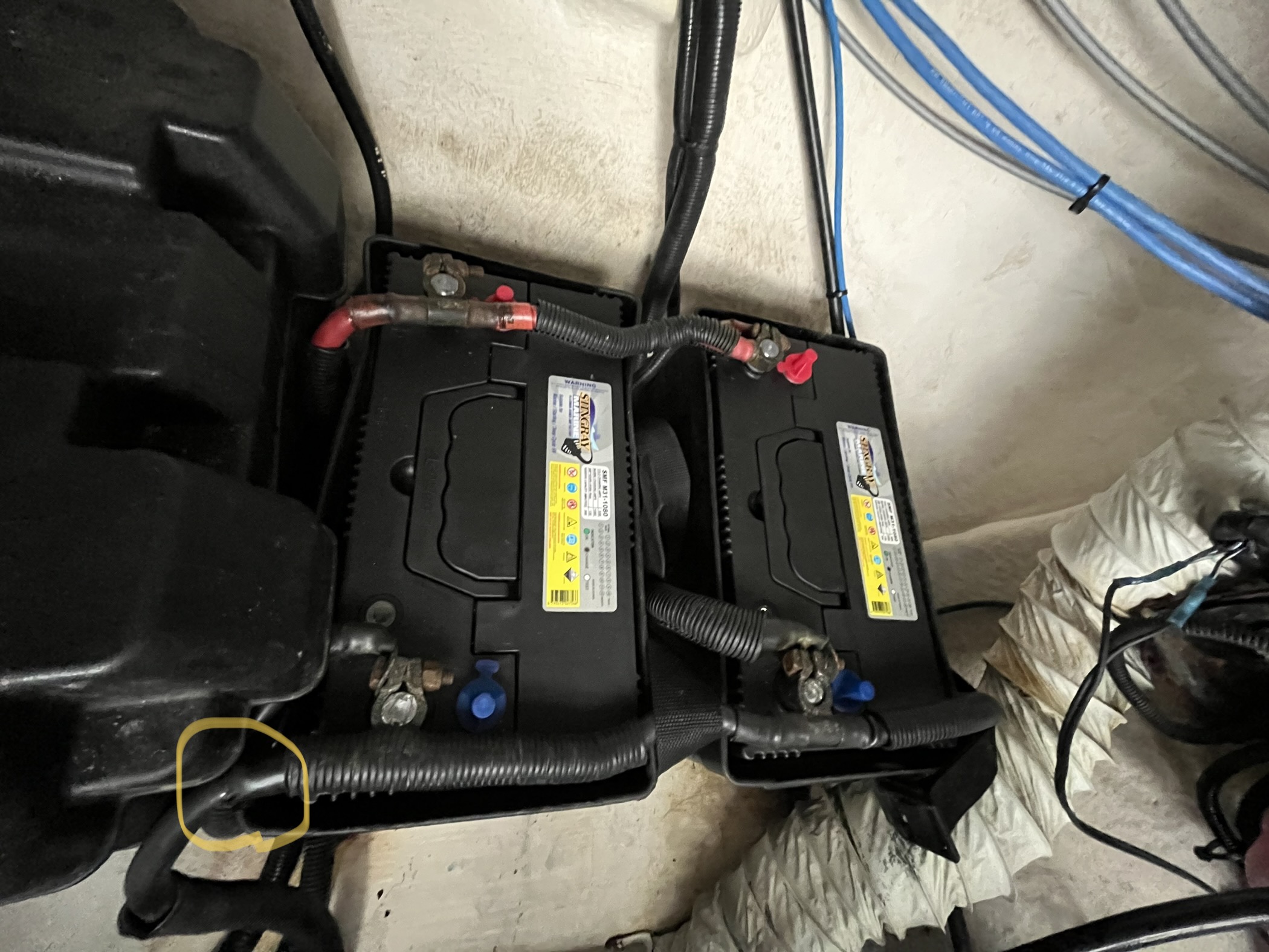
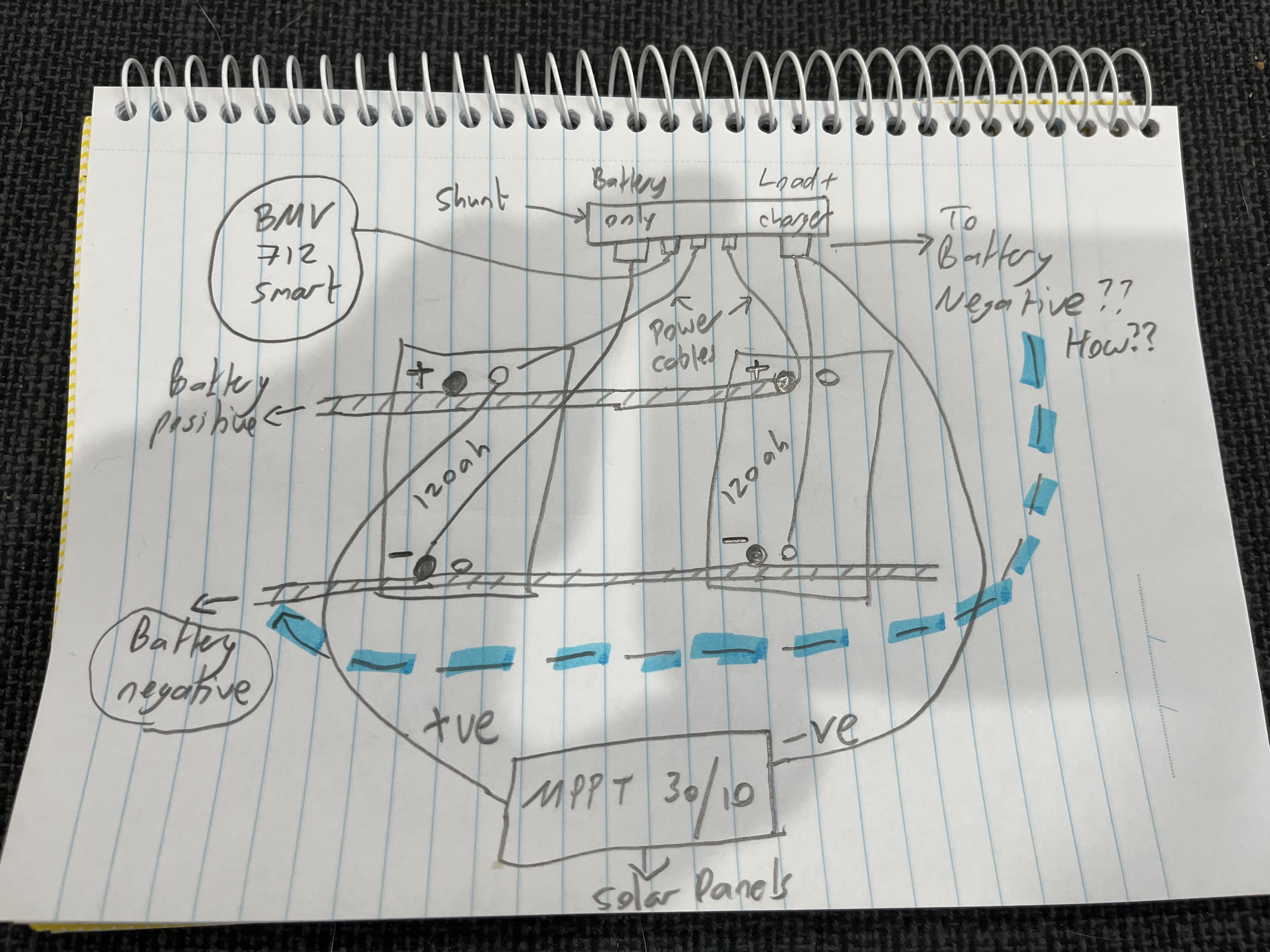
I am wiring up a 712 smart into a boat. I’ll try and explain my issue….I have 2 x 120ah house batteries wired in parallel as per photo. I have connected the negative terminal on the left battery to battery only terminal on the shunt as per instruction. Connected power cables to both batteries. Connected negative terminal of second battery (right in photo) to load and charger terminal on shunt. Connected positive cable from solar system mppt 100/30 to positive terminal on left battery and negative to load and charger terminal on the shunt. All good so far! See basic drawing.

My big problem is how to run the negative cable from the load and charger terminal (highlighted blue in sketch) back into boats DC system as the cable running from the negative terminal on the left hand side battery is huge (highlighted yellow in photo). If I don’t connect to it won’t have the full circuit? Hope this makes sense!


9af28e12-3ede-44a6-91bd-c9abf820d441.jpeg


BMV Battery Monitor
2 |3000

Up to 8 attachments (including images) can be used with a maximum of 190.8 MiB each and 286.6 MiB total.

7 Answers
Kevin Windrem avatar image
Kevin Windrem answered ·

From the sketch, it appears you have connected the shunt between the negative terminals of the two batteries without breaking any of the current carrying wires. That will not work. The shunt needs to measure ALL current in and out of the battery so you need to insert the shunt IN LINE with all loads and charging sources. as shown in the disgram provided by John Leslie.

2 |3000

Up to 8 attachments (including images) can be used with a maximum of 190.8 MiB each and 286.6 MiB total.

moorecat avatar image
moorecat answered ·

Sorry here’s the sketch…

7e52083e-a505-40b7-b894-5b65b6bf9c5e.jpeg


2 |3000

Up to 8 attachments (including images) can be used with a maximum of 190.8 MiB each and 286.6 MiB total.

klim8skeptic avatar image
klim8skeptic answered ·

You have 2 batteries, and 5 thick black cables connected to the 2 battery negatives.

Where do those 5 cables go/come from??


2 |3000

Up to 8 attachments (including images) can be used with a maximum of 190.8 MiB each and 286.6 MiB total.

moorecat avatar image
moorecat answered ·

Boat dc supply as far as I can work out!

1 comment
2 |3000

Up to 8 attachments (including images) can be used with a maximum of 190.8 MiB each and 286.6 MiB total.

klim8skeptic avatar image klim8skeptic ♦ commented ·

Boat dc supply as far as I can work out!

You are on site and can actually trace the cables to their origin.

Not something that can be observed from a single photo, and a dodgy mudmap.

0 Likes 0 ·
John Leslie avatar image
John Leslie answered ·

@Moorecat, if you have not already seen it, you might find Victron's Wiring Unlimited book a useful reference. Perhaps take a look at the battery section starting at page 16. It is hard to tell from your pictures of how all the loads and charge sources are being connected. But I believe best practice might be to have negative come off your parallel batteries from a single post that is diagonal to the single positive post on the other battery. Then (rather than connecting charge sources and loads to the shunt) the shunt sits isolated between the negative battery post and all of your other negatives . This could be achieved by the use of a negatives busbar or other arrangement. That might clean up your runs.

2 comments
2 |3000

Up to 8 attachments (including images) can be used with a maximum of 190.8 MiB each and 286.6 MiB total.

moorecat avatar image moorecat commented ·
Many thanks John. Any chance you could draw a quick sketch of that I’m pretty green to this stiff!
0 Likes 0 ·
John Leslie avatar image John Leslie moorecat commented ·

scratch2.jpg

From page 19 of the Wiring Unlimited book, which will explain why you wire it up this way for even charge/discharge. This diagram has four batteries to your two but otherwise the same.

scratch1.jpg

Taking liberties with the diagram in the BMV-712 manual - your goal is to make sure that the shunt 'sees' all of the negative return loads to the battery. The busbars become your wiring fan-out and collection points for the system, keeping the battery posts clean with single connections. You mentioned wire sizes, which are very important that you calculate correctly if you are adding new charge sources (MPPT?) or new loads. Same for fusing. All in the book. Hope this helps.

0 Likes 0 ·
scratch2.jpg (39.6 KiB)
scratch1.jpg (107.2 KiB)
moorecat avatar image
moorecat answered ·

Hi John many thanks is. I’m still a bit confused any chance if a quick sketch?

2 |3000

Up to 8 attachments (including images) can be used with a maximum of 190.8 MiB each and 286.6 MiB total.

John Leslie avatar image
John Leslie answered ·

Sure @Moorecat. However, I am not an electrician and so offer the sketch below for concept illustration only. You should consult with a qualified technician on your specific situation and design target. Improper electrical design, cable selection and fusing can cause fire, among other risks. Not included in this sketch are other important design considerations such as a battery isolation switch, bilge pump wiring, circuit breakers, grounding, galvanic isolation, etc.

sketchdrawio.png


sketchdrawio.png (88.0 KiB)
1 comment
2 |3000

Up to 8 attachments (including images) can be used with a maximum of 190.8 MiB each and 286.6 MiB total.

moorecat avatar image moorecat commented ·
Awesome thanks so much will get a sparky involved I think!
0 Likes 0 ·