I have my home batteries set up to provide off peak power to my heat pump but I really want it to feed into the house, could someone direct me to the instructions to set this up. I understand I need a current sensor but I’m not sure how and where to configure it, many thanks.
asked
Connecting to the grid, home system with 48v PylonTech batteries, multiplus2 and off peak charging.
Sounds like you want to setup an ESS? A good starting point would be this:
https://www.victronenergy.com/live/ess:quick-installation-guide
I have watched that and, unfortunately don’t see how to get the batteries feeding into my home circuits with out connecting them directly to ac out1 or 2. I have altered the Power Assist flag to ON but need some assistance from there. Thanks.
Takes a bit to get your head around this so ask away as needed, the AC Outs are optional if you want circuits that are battery backed up (essential loads), you only need the AC In connected for ESS, its 2 way, will charge and discharge back into your consumer unit to run the house on off peak electric. You will need an energy meter on the tails too.
Dupe...
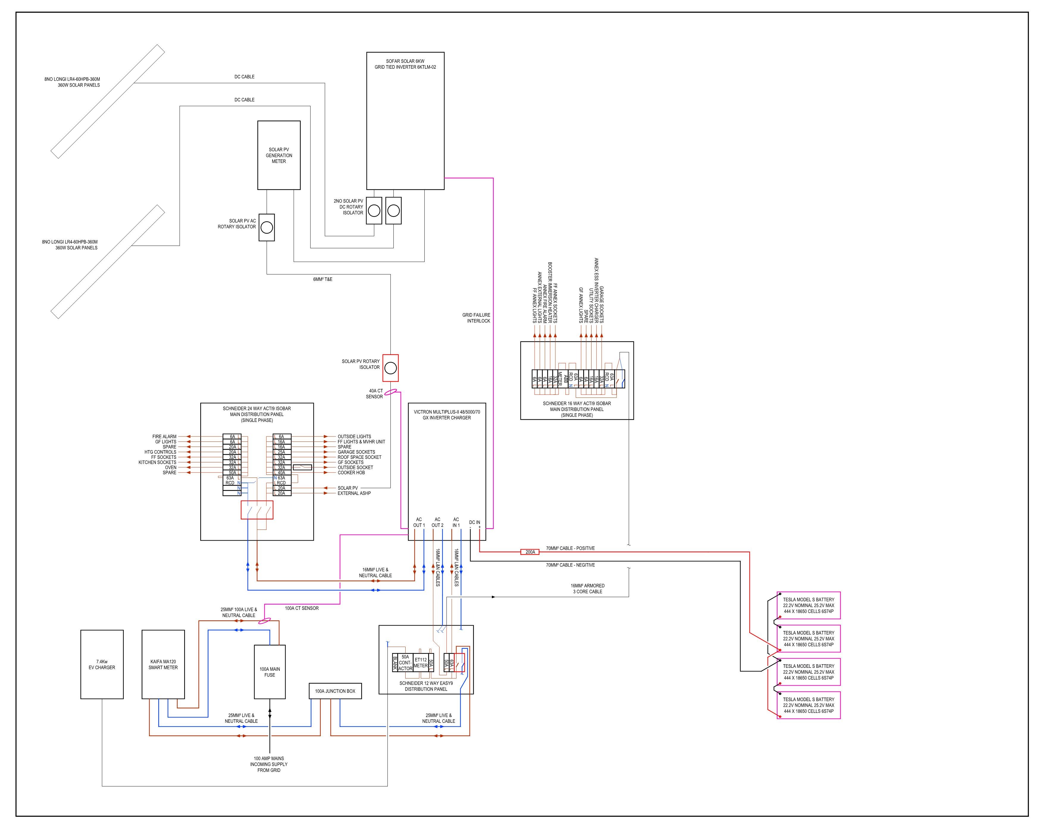
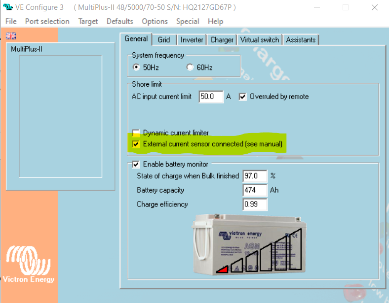
@Richard Weir I do currently have my current sensor on my mains tail between the meter and the main distribution board as shown on my below schematic. My whole house runs though my Multiplus therefore really I do not need a CT sensor as the sensor on the AC-in will do the job but as I have the system set up for power assist for the EV charger, I kept the CT sensor on the incoming mains tails between the meter and the main distribution board to allow power assist.
If you have loads on the AC-In side of the Multiplus, then put the CT sensor on the incoming mains tails to provide power assist to the loads you have on the AC-in side of the inverter and set the powrr assist to 1.0 in VE config.
 Hi @Jason - UK thanks once again for your help.
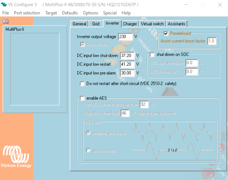
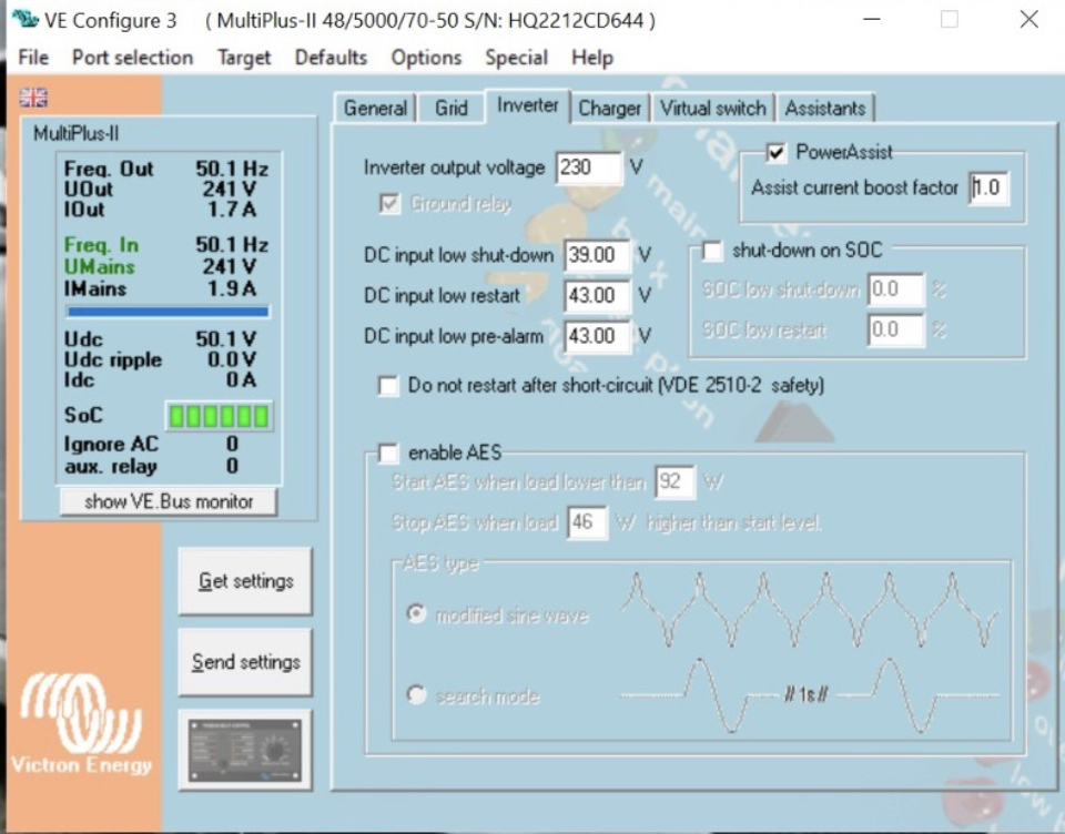
I have adjusted the inverter settings as per your, but kept my voltages slightly different. I see that you have all of your home circuits connected in a straight through design but I wanted to set up a parallel design where the batteries feed back to the circuits via the AC IN 1. Can you help with that? Thanks
@Richard Weir do you have a schematic of your system? I'm assuming you have set up the ESS assistant, if so, then with the CT sensor on your incoming mains cables, you should nearly be there if not working already.
Hi @Jason - UK I have the CT installed now and wired to Aux1 but don’t seem to have any further info on the screen about its connectivity or use. I’ve ticked the box in the config and uploaded the new file but again no change in how it’s working. I’m getting about 2vdc from the ct itself, just wondered if it’s got a specific polarity? Thanks richard.
@Richard Weir What CT sensor do you have? Is it the 100a Victron CT sensor with the 3.5mm jack on the end? Odd you have it connected to AUX1.
Under grid code settinfs in VE config on the 2nd tab, do you have the ‘Use AUX1 for grid control’ (or words to that affect) selected?

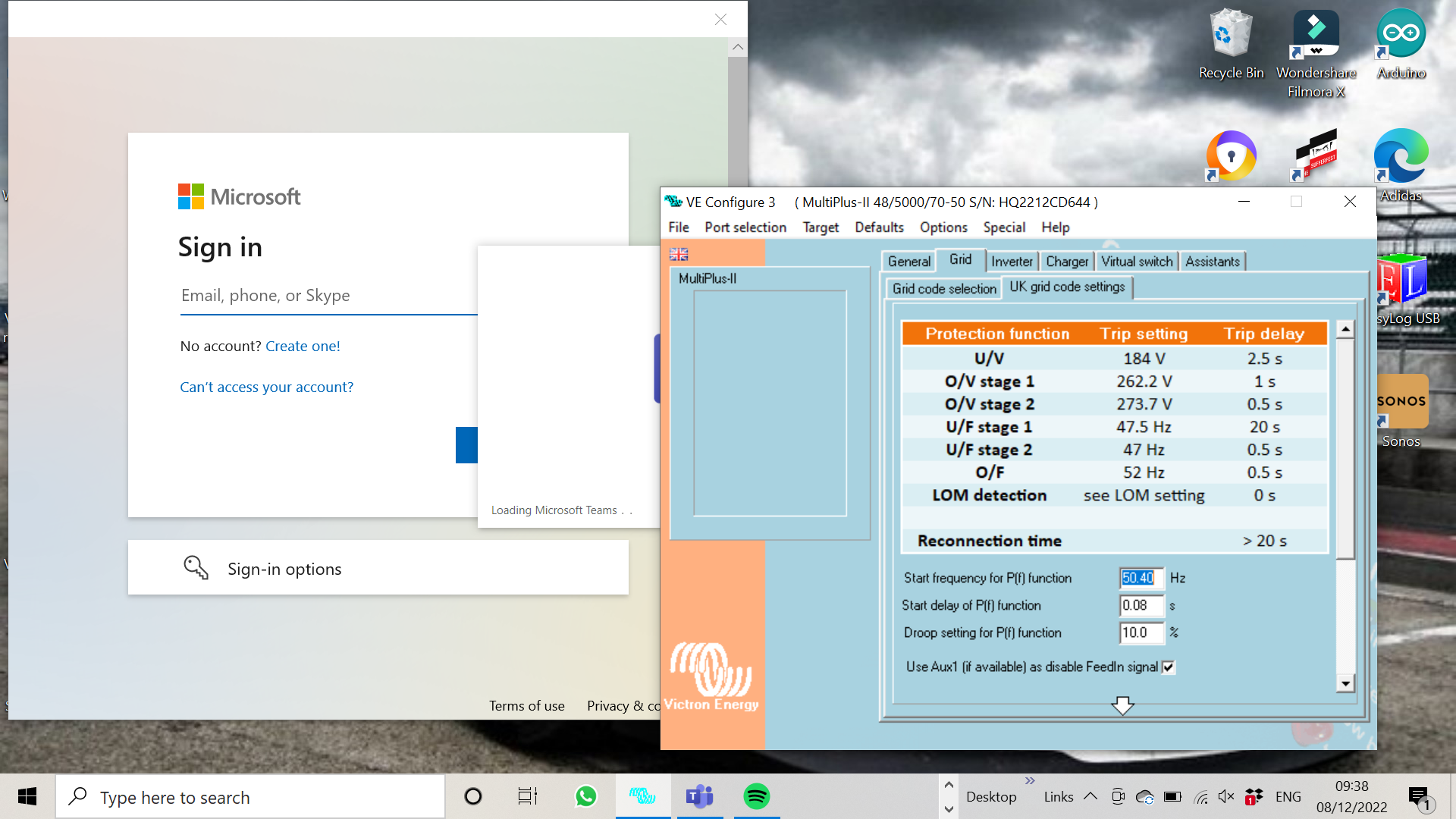
Here is the grid set up
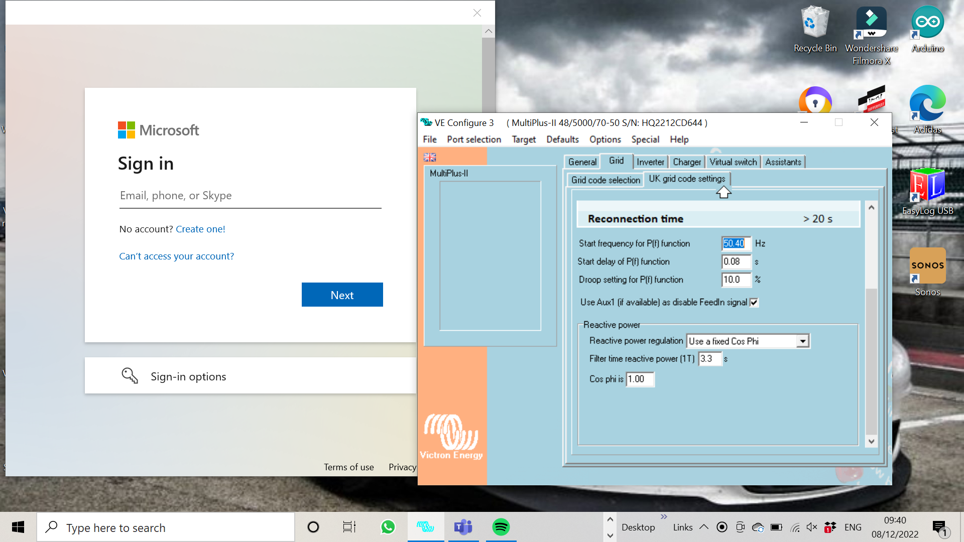
Here are the other parameters