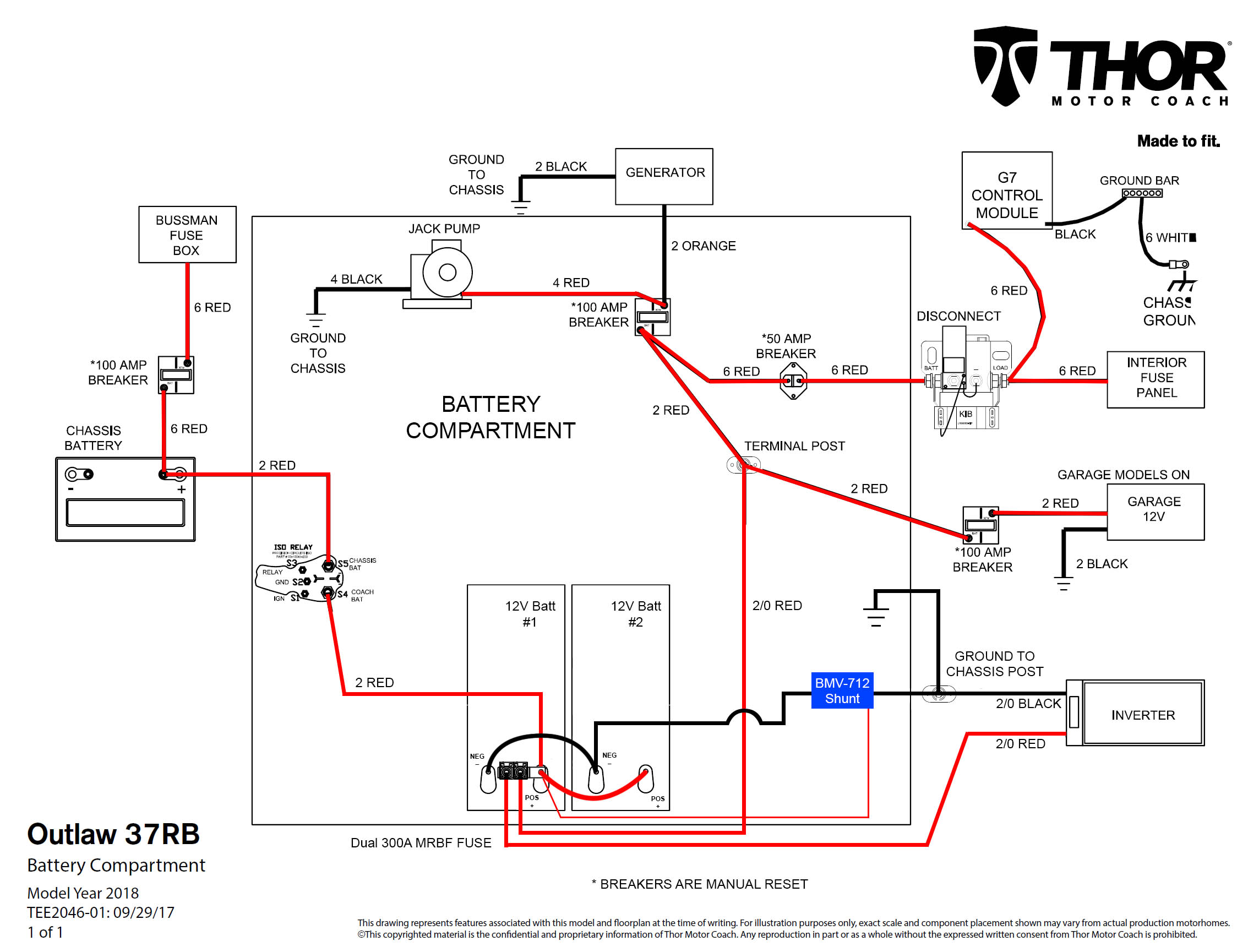
I recently switched our four 6V flooded batteries in our class A motorhome to two 12V lithium, and want to install a BMV-712 to monitor battery SOC. However, looking at the instructions, I'm having a difficult time figuring out where to place the smart shunt in our system. The instructions say to place in between the battery negative and all loads on the system. But our system has multiple chassis grounds, and only the inverter is directly connected to the battery bank -- all the other loads are connected to a different chassis ground. I'm relatively new at this, could someone give me a pointer on where the shunt should be installed? Do I place it in between the battery and the inverter like in the attached diagram? Or do I need to track down all of the chassis grounds and connect them all to the shunt? I looked through the forum posts and couldn't find an obvious match.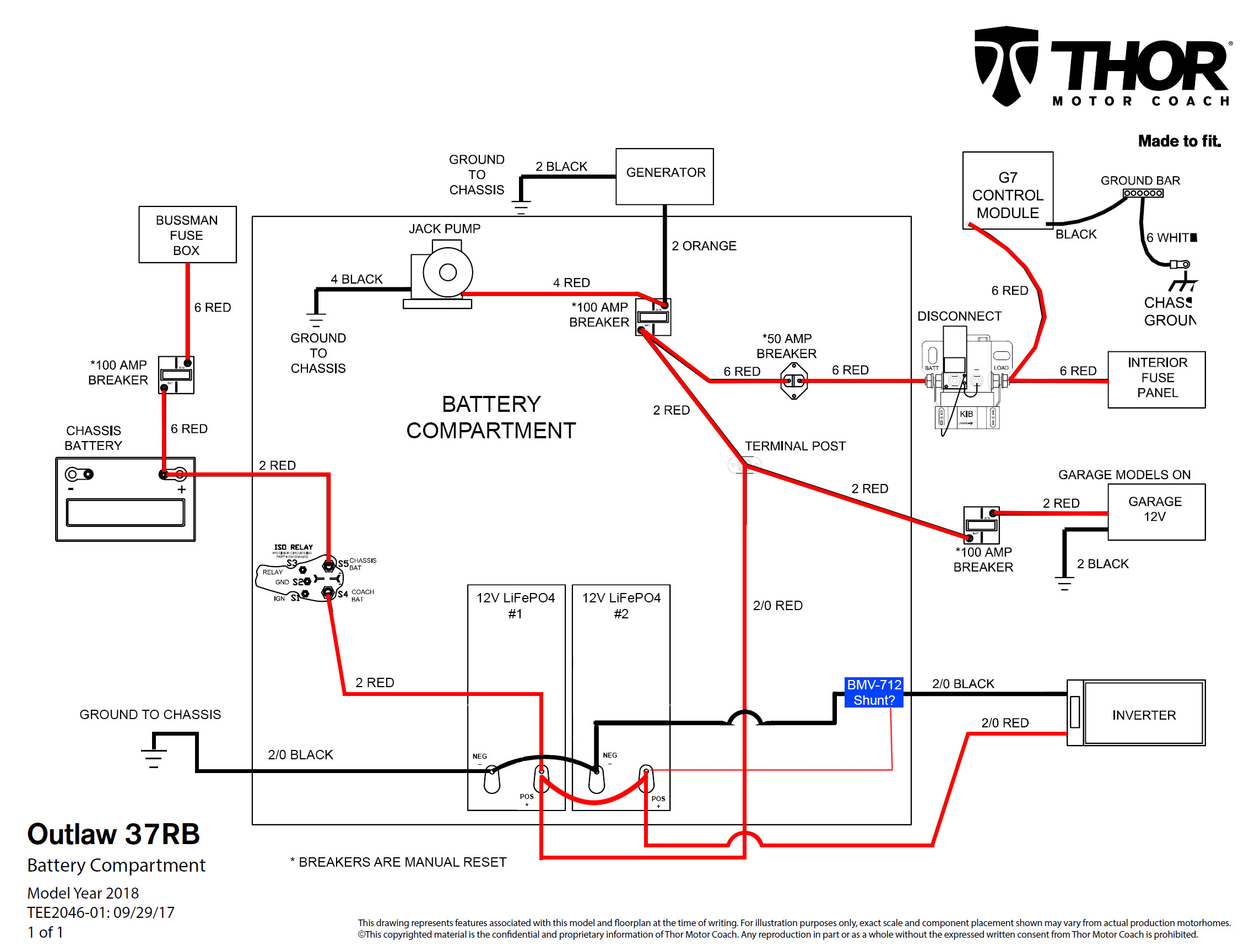
asked
BMV-712 shunt install location
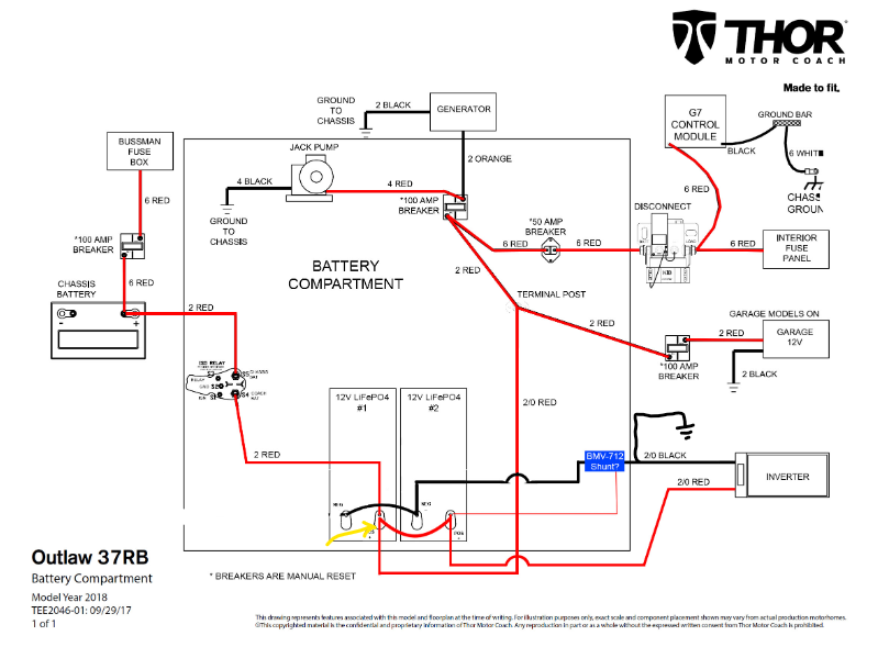
You have to move the battery chassis ground to the other side of the shunt.
I would also move the inverter positive over to the other battery for even battery loading/charging current. It should also be fused (not shown).
You would need to remove the house battery connection to ground (on the left side of your drawing), and then connect the ground to the load side of the shunt, where the inverter negative is connected. Then it will measure the charge current as well as the discharge current.
I need some expert advice. My Victron Smart Shunt is installed correctly but some people on our FB page is providing bad one on one installation as well as youtube video instructions. They are connecting the negative inverter/charger to the ground and adding a wire that runs from the ground to the load side of the shunt. What is the downside of doing this? I know it's not right but I want to have a reason why because it seems to be working correctly as far as their concerned. See image. Thanks in advance.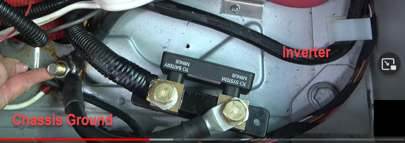
There's only one reason. Lack of understanding. Could be compounded by other factors.
If you're unsure, ask in this community. There aren't many wrong answers given and usually someone will notice and correct if one does happen.
My post is the inquiry. Thanks for replying but I'm looking for answers.
@jhayes Thanks for replying but I'm looking for answers.
The answer is as always,
The shunt can only measure current that flows through it. If you connect a chassis ground to the battery you are bypassing the shunt, and current / SOC values are not correct.
Sorry, misread your question. Electrically it's the same. But the neg ground to shunt needs to carry full load/charge current and increases the length of the charge neg path. It's also messy. Ideally load side of shunt goes to a busbar, charger and all other negs connect to the busbar. This avoids/lowers the risk of earth/ground loops.
Also see @klim8skeptic comment.
Some say better not to carry heavy current through the chassis. Not sure how good the claim is.
Ah, I see. I noticed the positives were swapped and I fixed that, thank you!
The chassis ground that's off the battery #1 in my drawing is connected to a terminal post in the battery bay. If I'm understanding you both correctly, what I could do is this:
- Remove the chassis ground from battery #1
- Connect the inverter neg to that chassis ground terminal post
- Connect that same terminal post to the load side of the shunt
- Connect the battery side of the shunt to the negative on the battery #2
Would that do it? I appreciate the help. I can update my drawing when I get home
Also, the diagram from Thor for the model year following ours shows a 300A MRBF fuse off the battery positive to inverter. But our coach didn't come with one. Is that what I should add there? I guess it's possible they placed the fuse somewhere else.
There should be a fuse to protect the cabling close to the battery.
Bad things happen should the cable get damaged, then shorts the battery out...
OK, I updated my drawing with (I think) are the given recommendations. My plan was to connect the both the inverter and shunt to the existing ground post that's mounted in the battery bay. Does this look correct? Thanks in advance!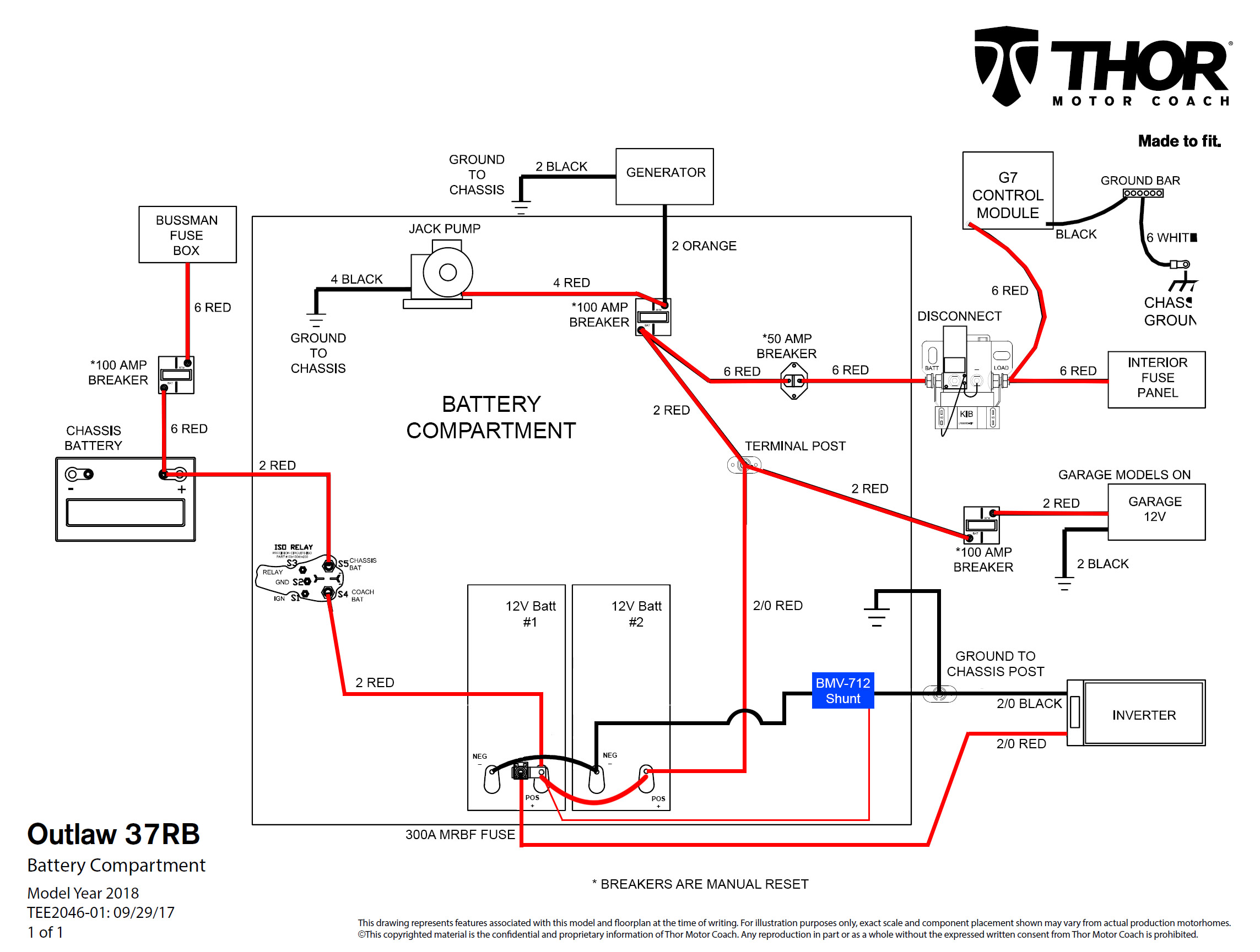
Relocated chassis ground is good.
The other positive lead also has to be on the left battery + post . Should also be fused.
Interesting. I did not know it was OK to do all them on one post since the stock install had them across two batteries. So I should use a dual fuse terminal like this? I appreciate all the help, I am learning a lot.
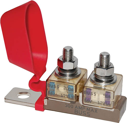
That dual fuse holder looks like an ideal solution.
Your diagram looks spot on.
Good Luck.