question

jjv avatar image
jjv asked

Pre-Charge Issues

I am in need of some guidance regarding the steps necessary to properly pre-charge a Multiplus 3000 attached to a 24 volt battery. I have found very little credible information available regarding this topic. After having built a Victron system, I am now finding that even with the use of two different resistors, attempting to connect the battery cable results is a substantial spark. The following summarizes the steps I have taken this morning:

Connect the hot 2/0 cable to the battery.

  1. Turn on the Blue Sea Systems M Series Battery switch, leaving on during the following two steps.
  2. Attach a 50 watt\25 ohm metal cased resistor to the black 2/0 battery cable, then touching the negative battery post to the resistor contact for 10-15 seconds (clicks are heard from the Multiplus, lights on the Victron shunt, distributor, Cerbo GX, and Victron Smart Solar 150\45 MPPT etc light up).
  3. Disconnect the resistor from the battery post and remove, attempt to connect the black 2/0 battery cable to the negative post.

After experiencing a substantial spark, I attempted to complete the above process using a metal 100 watt\2 ohm resistor instead, having the same results.

Can someone provide me with guidance? Am I not following the correct steps to properly pre-charge the Multiplus?

setup
2 |3000

Up to 8 attachments (including images) can be used with a maximum of 190.8 MiB each and 286.6 MiB total.

6 Answers
nickdb avatar image
nickdb answered ·

The easiest way, since you have a solar charger, is to connect it all up, leave the battery and inverter off and turn on the mppt. Let it precharge from the solar, then turn on the battery etc.

The other thing to consider is that the 3kVA is not overly large, so depending on your batteries, you might get away with not precharging it.

2 comments
2 |3000

Up to 8 attachments (including images) can be used with a maximum of 190.8 MiB each and 286.6 MiB total.

andreas-siebenmorgen avatar image andreas-siebenmorgen commented ·

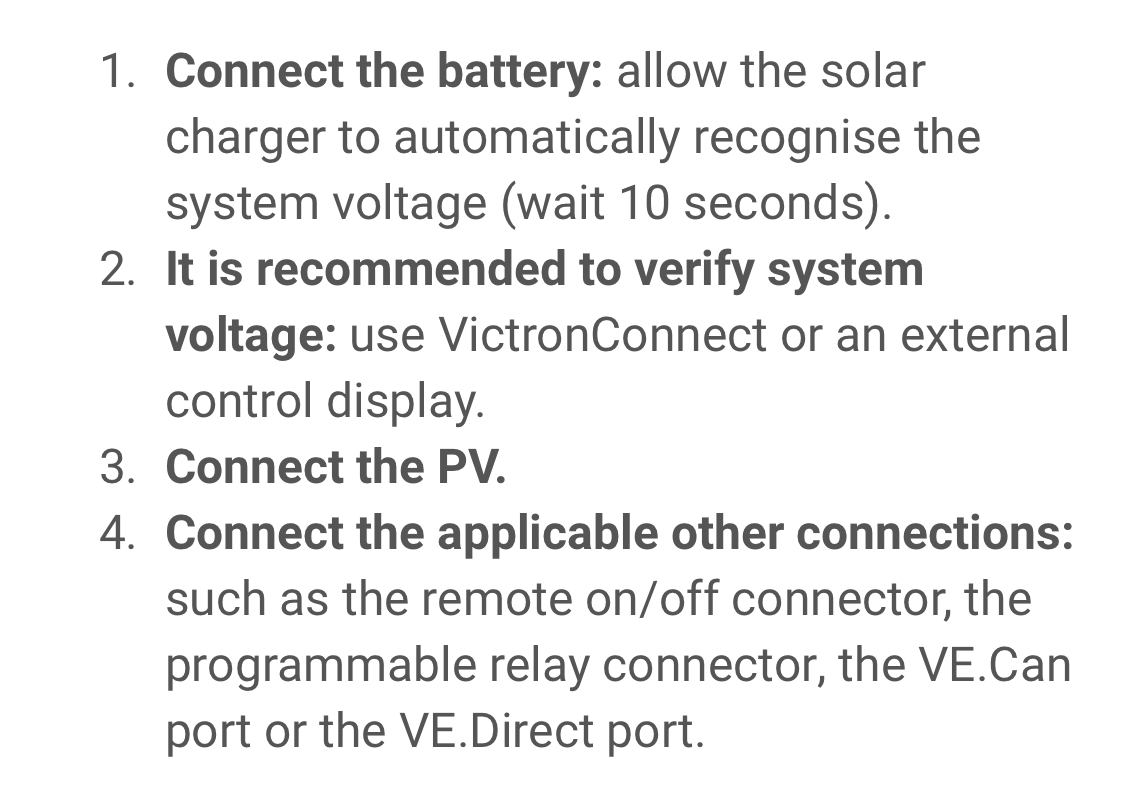
I don’t think this is a good idea because the MPPT manual states clearly that the battery has to be connected to the mppt before you connect the PV panels, to lock in the right system voltage.

img-9412.jpeg

0 Likes 0 ·
img-9412.jpeg (273.4 KiB)
nickdb avatar image nickdb ♦♦ andreas-siebenmorgen commented ·

This is to prevent new mppts from detecting/selecting the wrong battery voltage. Pre charging via mppt, done properly, is a good alternative.

All about context.

1 Like 1 ·
jjv avatar image
jjv answered ·

Thank you Nickdb. So this leads me to the question, are my above steps not correct assuming panels are not yet connected?

1 comment
2 |3000

Up to 8 attachments (including images) can be used with a maximum of 190.8 MiB each and 286.6 MiB total.

nickdb avatar image nickdb ♦♦ commented ·


You did have the inverter turned off, right?

0 Likes 0 ·
pwfarnell avatar image
pwfarnell answered ·

If you disconnect the resistor but have other power users connected to the system as you list then these will be powered by discharging the Multiplus capacitors. I thought with a precharge circuit that you keep the precharge resistor connected until you connect the main feed.

2 |3000

Up to 8 attachments (including images) can be used with a maximum of 190.8 MiB each and 286.6 MiB total.

tk-421 avatar image
tk-421 answered ·

How I do it:

1. All equipment and disconnect switches off

2. All wiring connections in place

3. Clip a voltmeter onto the DC input terminals of the Multiplus

4. Bypass the battery disconnect switch using the resistor, note that voltage begins to rise on the input terminals

5. When input terminal voltage stops rising and is very close to normal battery voltage, close the disconnect switch. (If it doesn't get to normal battery voltage, the resistance value of the resistor is too high, or something was left on by accident.)

6. Disconnect resistor and voltmeter

7. Turn on equipment

3 comments
2 |3000

Up to 8 attachments (including images) can be used with a maximum of 190.8 MiB each and 286.6 MiB total.

Fideri avatar image Fideri commented ·
@TK-421 All seems clear except Step 3. Noting that I have a Quattro instead of a Multi (I thought they were the same in this aspect), the DC input terminal on the charger/inverter takes the battery. How then can you connect there a voltmeter? Or the latter shares the terminal with the battery?
0 Likes 0 ·
tk-421 avatar image tk-421 Fideri commented ·

I use test leads with alligator clips to connect to the flat portion of the cable lugs, and then connect the other end of the leads to the probes of my multimeter. You could also connect such leads to the threaded post of the terminal itself, if you get ones with big enough clips. And if the terminals on the device are hard to get to, connecting to the other end of the wires attached to those terminals works fine as well, e.g. one connection on battery (-) and one on the inverter side of the disconnect switch that is in the middle of the (+) connection.

0 Likes 0 ·
Fideri avatar image Fideri tk-421 commented ·

@TK-421 that makes sense, thank you.

On a related matter, I read on this forum that someone used an AC 120V 100 watt incandescent bulb in place of a resistor successfully because that is what was available. I found that weird. I would have used a DC bulb of appropriate voltage, 48V in my case.

Any thoughts?

0 Likes 0 ·
jjv avatar image
jjv answered ·

Thank you tk-421. Your approach makes more sense than what I am doing. However, my connections for the Cerbo GX and controller are direct to the Victron Distributor. How do you normally keep those two devices from drawing voltage from the Multiplus capacitors during pre-charge? Also, just to be sure, what position do you have Multiplus on\off switch in?

1 comment
2 |3000

Up to 8 attachments (including images) can be used with a maximum of 190.8 MiB each and 286.6 MiB total.

tk-421 avatar image tk-421 commented ·
I don't have either of those, but I do have a few other things connected to the DC bus, like a backup inverter and backup charger. I just make sure they're all off, and the Multiplus switch is in the off position as well. I don't know if the Cerbo or controller have a physical power switch you can turn off.
0 Likes 0 ·
jjv avatar image
jjv answered ·

Thank you tk-421. Ignore my above question, I had to stop and think a moment, realizing the disconnect switch is in the off position and the current is bypassing the Cerbo GX and controller.

2 |3000

Up to 8 attachments (including images) can be used with a maximum of 190.8 MiB each and 286.6 MiB total.

Related Resources

Additional resources still need to be added for this topic