question

catweazle avatar image
catweazle asked

Parallel batteries damaged from overcharging

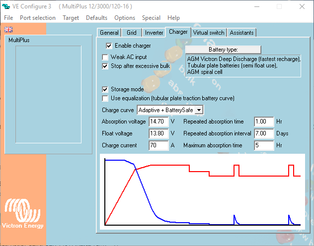
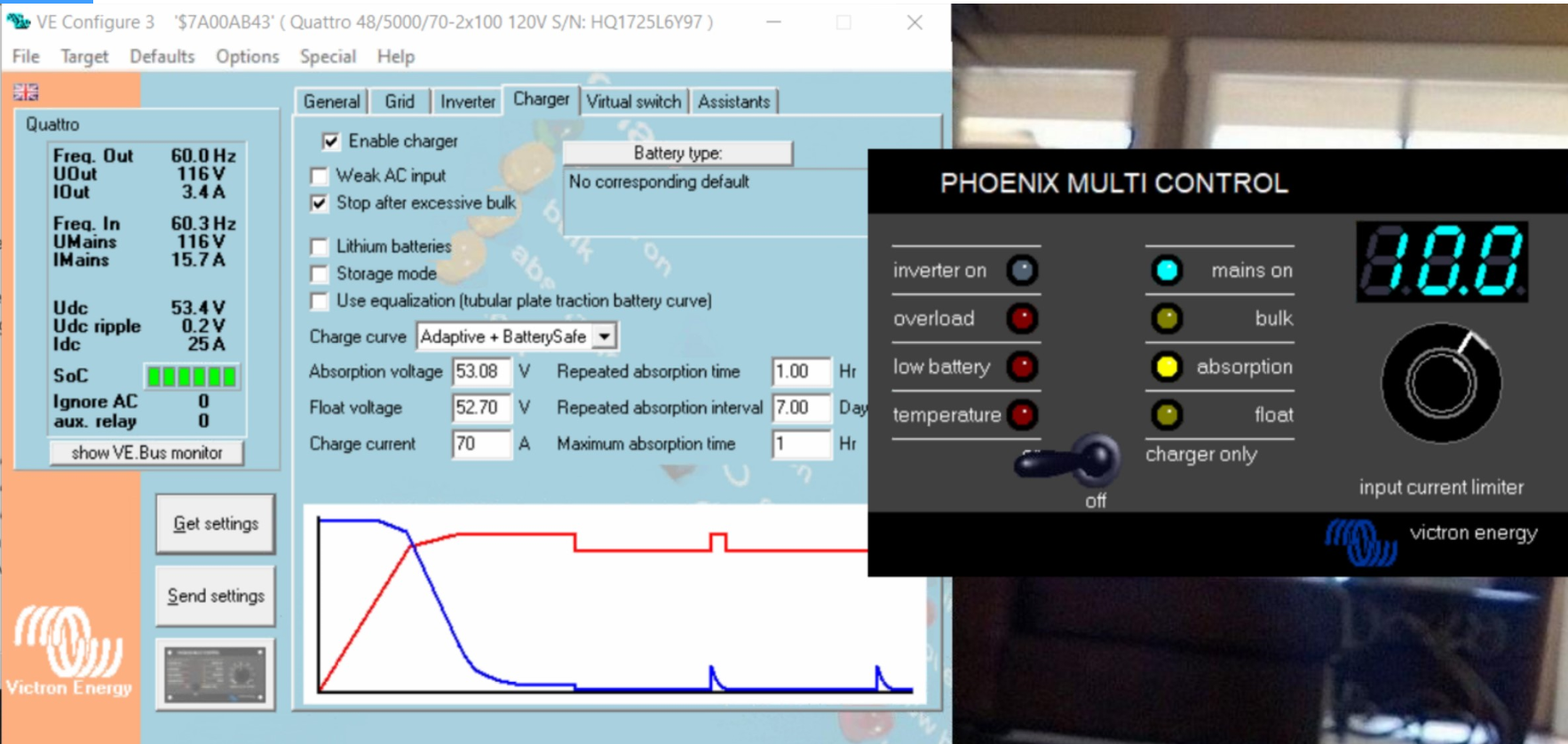
We had our system checked and the VE engineer set the ABS to 14.70 and the Float to 13.8.

However, the batteries have been charging at 15.75v and they're now cooked. How could this happen? He has sent me a screenshot to show the settings so I don't think he's done anything wrong. The batteries are: VE AGM supercycle 125a x 6.


battery charging
image.png (45.0 KiB)
2 comments
2 |3000

Up to 8 attachments (including images) can be used with a maximum of 190.8 MiB each and 286.6 MiB total.

boekel avatar image boekel ♦ commented ·

What temperature was there when charging? and do you use a temp-sensor?
Also: do you use sense wires to the battery?

0 Likes 0 ·
novice avatar image novice commented ·
0 Likes 0 ·
5 Answers
digima avatar image
digima answered ·

You mentioned that the battery model you use is VE AGM supercycle, and the battery type indicated in the screenshot is VE AGM Deep Discharge (including other types).

Is this the right setting for your battery model ?


12 comments
2 |3000

Up to 8 attachments (including images) can be used with a maximum of 190.8 MiB each and 286.6 MiB total.

catweazle avatar image catweazle commented ·

That's a good point, but it seems that profile is Kind of the super cycle batteries. Having now looked at the history on the new battery monitor is shows they've had 20V at some point in the last 3 weeks. So, no wonder they're cooked. But I need to find out how that happened. Really odd. Any ideas gratefully received.

0 Likes 0 ·
boekel avatar image boekel ♦ catweazle commented ·

What other components are in the system?

0 Likes 0 ·
catweazle avatar image catweazle boekel ♦ commented ·

There is 550 amps of solar panels fed through two VE 100/30 but they shouldn't cause the voltage to exceed the 14.7 that was set. The VE engineer apparently checked them out as well.

0 Likes 0 ·
boekel avatar image boekel ♦ catweazle commented ·

What kind of setup is this? home / boat / rv / ??
Do you have pictures of the installation?

0 Likes 0 ·
catweazle avatar image catweazle boekel ♦ commented ·

This is on a boat. It is hard to show photos but the 6 service batteries are in parallel. There are two Multiplus 3000 inverters. The batteries can be charged off the engine alternator, the solars, the generator or off shore power. Only shore power has caused this problem of overcharging. The VE engineer confirmed the solar VE MPPT's are good. The batteries were only installed a year ago by a certified engineer, everything was checked then. The local electrician has confirmed 5 of the 6 batteries are dead and that we've had 20v max input since the new battery monitor has been installed.


0 Likes 0 ·
JohnC avatar image JohnC ♦ catweazle commented ·

Don't read too much into a 20V recorded spike. Could just be a transient thing. You'd need to monitor V to be sure, no gain in guesswork.

I'd suggest a more serious issue for you is the 6x parallel batt strings. I'd be offering them a much 'softer' charge profile, like maybe 14.2V max. Or even less.

And then monitor them regularly with even a 'touch test' for temp.

Imbalance is your worst enemy. They just die one after the other..


0 Likes 0 ·
catweazle avatar image catweazle JohnC ♦ commented ·

Thank you very much for taking the time to answer. Sadly I have had no luck from VE themselves so far. I have to admit I did think 14.7 seemed very high. In fact, the two lights battery safe mode came on immediately, but the engineer didn't seem to think it was a problem. So, I will wait for the Italian engineer to come and maybe they'll replace the batteries. Thanks again for your help.

0 Likes 0 ·
boekel avatar image boekel ♦ catweazle commented ·

I'm tempted to say: get another Victron specialist to double check the inverter, and especially the MPPT's I don't think the inverter is capable of outputting 20V unless it's very broken.

The MPPT's are very well capable of outputting 20V, and if batteries are fully charged by shore power, MPPT's could push them over the limit if not well configured.

0 Likes 0 ·
catweazle avatar image catweazle boekel ♦ commented ·

Hi - the MPPT's were supposedly checked at the same time by the registered Victron Energy engineer. The VE engineer in Italy is now saying that because their technician hasn't caused the issue, and because the screenshot doesn't show an error, and because we have had to reconfigure the multiplus to the book settings, the batteries will not be covered under warranty.

So, we had them checked out by a Victron engineer. He changed something and now they're dead, but we will have to buy new batteries. That doesn't seem fair or right to me?


0 Likes 0 ·
boekel avatar image boekel ♦ catweazle commented ·

Hi @Catweazle, this is a very sour deal indeed.
I've had batteries cooked once: my temperature sensor was on one bank, and this bank was disconnected - the other bank wasn't monitored and cooked.

Problem is: as battery temperature rises voltage should be lowered, and when it isn't the battery will cook, 14,7V is a very high voltage already so if a battery heats up above 'room temperature'

Personally I think it is unwise to not have a temperature sensor in an installation like this, it is even included in delivery with most (or all?) Multi's / Quattro's.

Recommended absorbtion voltage is 14,2 - 14,6 V, the lower the charge rate the lower this voltage should be,
14,7 V is for a short high power charge ('fast charge').
https://www.victronenergy.com/upload/documents/Datasheet-GEL-and-AGM-Batteries-EN.pdf

quote:
14. Effect of temperature on charging voltage The charge voltage should be reduced with increased temperature. Temperature compensation is required when the temperature of the battery is expected to be less than 10°C / 50°F or more than 30°C / 85°F during long periods of time. The recommended temperature compensation for Victron VRLA batteries is -4 mV / Cell (-24 mV /°C for a 12V battery). The centre point for temperature compensation is 25°C / 70°F.

The above means that when the batteries reach 40°C the charge voltage should already be 0,36V lower, 50°C = 0.6V lower, 60°C = 0.84V lower
You see that it's easy to kill batteries...most batteries don't die of natural causes.

0 Likes 0 ·
catweazle avatar image catweazle boekel ♦ commented ·

A temperature gauge is on my shopping list for when the new batteries arrive. Do you think the VE engineer who set the charge voltage at 14.7 has caused an increase temperature that could have cooked the batteries?

0 Likes 0 ·
boekel avatar image boekel ♦ catweazle commented ·

I can only point to the datasheet:

'Temperature compensation is required when the temperature of the battery is expected to be less than 10°C / 50°F or more than 30°C / 85°F during long periods of time.'


0 Likes 0 ·
dwmarine avatar image
dwmarine answered ·

Is a temperature sensor fitted that is connected to the Multiplus?

What enclosure are the batteries in? How much venting is there?

What is their average and peak temperature? Can you touch them while charging?. Has the charge voltage been derated for ambient temperature above 25deg/c? if the enclosure gets to that?

How much air gap is between the batteries?

Can you please post a photo of your battery install?

Are the solar chargers set to 12volts, not 24?

I have had a couple of installations lately where the last person had batteries mounted too close together without temp compensation on the charger, causing thermal runaway.

It's not nice trying to explain to a client why his 8 Lifeline batteries are toast.

Agree with Boekel on his comments.

Any answers you can gather to these questions would help greatly

Darren

9 comments
2 |3000

Up to 8 attachments (including images) can be used with a maximum of 190.8 MiB each and 286.6 MiB total.

catweazle avatar image catweazle commented ·

Dear Darren

I think you might be right. The batteries are pretty tight in the two fibreglass boxes. They are touching each other. Please see photos. We don't have a battery temperature sensor (although this is something we will now install). The solar chargers are definitely set to 12V. Maybe when the VE engineer changed the settings to fast charge the extra temperature caused by this setting could have caused the damage? They have been ok for the last year at a lower charge setting.

0 Likes 0 ·
JohnC avatar image JohnC ♦ catweazle commented ·

Oh my.. I don't much like paralleled batts under perfect conditions, and your's haven't been given that. Wiring I mean.. http://www.smartgauge.co.uk/batt_con.html

0 Likes 0 ·
catweazle avatar image catweazle JohnC ♦ commented ·

What do you mean - wiring? We paid extra last year in France to make sure the wiring was balanced and right for our new batteries?

0 Likes 0 ·
catweazle avatar image catweazle catweazle commented ·

Do you mean the wiring of the monitor or the actual batteries themselves?


0 Likes 0 ·
JohnC avatar image JohnC ♦ catweazle commented ·

The batt wiring.. Sure they may be large wires, but true balance is a real challenge to achieve with 6x in parallel. In fact it's almost impossible. Please read the link I posted. Tis why I suggested a softer charge profile.

Boekel also stressed temps. And I agree. So which batt do you add the temp sensor to given natural imbalance, when the hotter batt will develop less resistance and get even hotter with more current flowing - until it dies.

And it's neighbour stays cool.. and the hot batt may be the fittest, but it dies first.

I have an auxiliary 4x parallel bank of old batts doing light duty, that I expected to die early. I give em a soft charge, and they've lasted way longer than expected.


0 Likes 0 ·
catweazle avatar image catweazle JohnC ♦ commented ·

So, how should new batteries be wired? Or wire the same with a much softer profile, plus a temperature sensor?

0 Likes 0 ·
JohnC avatar image JohnC ♦ catweazle commented ·

750Ah @ 12V is a substantial bank. In 6x strings with no 'midpoint' to monitor, a bit of a gamble. I can't help that, such is life..

I could suggest stuff that mightn't physically fit, like 6V or 2V batts, or Li's with their own bms. The stepup will invariably cost, and mightn't find your favour.

If you replace your existing setup with similar batts, wire them optimally and treat with kid gloves.

0 Likes 0 ·
catweazle avatar image catweazle JohnC ♦ commented ·

I don't think we can argue for different batteries from VE, so it is likely we will be getting the same. The Li's are horrendously expensive and out of our price range. I think treating new batteries with kid gloves is the only option. ie try and keep them cool and keep the charge cycle low.

0 Likes 0 ·
catweazle avatar image catweazle JohnC ♦ commented ·

That is a very interesting article you posted. It seems that the original set up was the positive at one end of the 6 and the neg at the other end - as per option 2 on the data sheet. However, in Malta we had a new battery monitor installed and he installed a new shunt. Because the neg cable was cut, the neg now comes of battery 4. He said it didn't matter, but it clearly does.

0 Likes 0 ·
Paul B avatar image
Paul B answered ·

Catweazle, If I may so bold and if you HAVE not already purchased the new batteries, Have a very good look at changing to lithium phosphate batteries.

1/4 the weight 1/4 the size and they usually come with a Battery management system that WONT allow you to damage them, yes they maybe double the cost but they will last for ages and ages

if you have 6 lead acids then to achieve the same amp hours of usable capacity you only need 2 lithium's phosphate on balance.

plus if you are running 2 x 3000 multiplus inverters then I think its a must that you change away from the lead acid ones.

you could be over cycling the lead acid ones as well as they are only good for 500 cycles on average.


the lithium's phosphate are usually good for 2000 down to 80 to 90 % discharge levels per cycle and then after the 2000 cycles they still have 80% of there original capacity.

I am a big fan of these especially on BOATS we have been putting them in now for 7 years and have still not had ONE failure in that time


Thge advantages for a boat are imense

Ie

1. they dont get hot at the levels a boat uses them even if air cons are used

2. they charge 20% quicker, ie on a lead acid if you discharge out say 100 amps for 1 hour then you charge 125 amps for 1 hour top bring them back up (not 100% correct but close enough)

Lithium phosphate - take 100amps out put back 105 amps

3. 1/4 the size and weight

4. you can discharge them down from 100% to 10% without damage DAILY if you want

5.they come with a BMS that balances the cels and shuts the system down if a undercharge happens or a overcharge

6. basically all the charging systems are compatible.

7. yopu can discharge and charge at very high currents without damage

8. in a lead acid the last 20% of a full charge takes 4 hrs, in a lithium phosphate its about 5 to 10 min, so the alternator puts out MAX amps until they are full. Not so with a lead acid


Ie you have 750 amp ours in 6 batteries max you should use is 50% so usable is 375

2 x 200 amp Lithium phosphate batteries would replace all those so 400 amp hrs of which the max you should use is 360 amp hrs


2 |3000

Up to 8 attachments (including images) can be used with a maximum of 190.8 MiB each and 286.6 MiB total.

Jmarc avatar image
Jmarc answered ·

We just had the same issue. Two 48/5000/70 in parallel connected to a set of lithium battery. We were investigating why the Lithium battery BMS kept tripping on over-voltage. Using Ve.Config multi we lowered the Voltage set point on both unit and started to charge. The Quattro started to charge at 25A each. Current and voltage were verified by the BMS and voltmeter. Here is a screen shot of the system while charging:

You can see that the Quattro is pushing 25A while the voltage was 0.3V above the Absorption voltage. In prior incident the Quattro pushed the voltage as high as 55.89 V at which point the BMS disconnected the battery on overvoltage.

Each unit has a temperature sensor connected to them.

Unit are normally connected to a CCGX. They are not in the picture above to allow Ve.Config proper operation. Software version was 2753413.

We did a firmware upgrade of both unit to 2753433 and reloaded the set-up. It all worked as expected. Once the voltage reached the absorption voltage the Udc stayed exactly at the setpoint and the current decayed slowly.

Any idea if the firmware upgrade is/was the solution or is there something else happening?


1583597825087.png (1.4 MiB)
3 comments
2 |3000

Up to 8 attachments (including images) can be used with a maximum of 190.8 MiB each and 286.6 MiB total.

Hi @Jmarc@aeandmengineering.com

It's not very clear what exactly is happening, but when troubleshooting, always update to the latest firmware (433 is very old).

Anyway: I don't see 'lithium batteries' selected in ve.config, so temperature compensation might be a reason for a higher charge voltage.

What lithium batteries are in this system?

Most 48 volt Lithium batteries have CANbus communication, and will take over the charge voltage settings over the configured settings in the inverters.


If you have more questions, please make a separate topic, as the topic your posting in is quite long (and about Lead/acid batteries) and your question is kind of buried away in it.

0 Likes 0 ·
Jmarc avatar image Jmarc Daniël Boekel (Victron Energy Staff) ♦♦ commented ·

Hi Daniel,

Thank you for your response. The system is on a Greenline boat with Greenline batteries. Set-up is from factory as far as I know. I will review with them the choice of battery type.

Can you clarify the usage of the temperature compensation. It does look like that until rev 460, the Coefficient was fixed. I tried to use the table in appendix F to see if it could be the cause of our problem but I cannot really understand the chart. they are two curves and two scales apparently for 12 and 24V systems but no indication of what is what. Supposedly the voltage are set for 25 DegC but the chart only show multiples of 10. So it is almost impossible to even guess estimate the correction on a 48V system. in our case the temperature was 10 DegC. So 15 Deg below setpoint. If I interpret the chart this would mean about 1V correction at 48V. The overcharge exceeded 1.5V. Is my interpretation correct?

Reading the manual I also noticed that only one sensor should be used in a parallel system. What is the consequence of having two like we have?

But in general I agree with you there should not be any temperature compensation for lithium. In our case should we even have sensors? or does the Quattro use the measurement to provide High and low temperature protection when Lithium is selected?

I did realized later that 433 was not the latest it was the last one I installed a year ago. We will install 469 as soon as possible.

As far as I know the BMS used on this boat has canbus but it is not compatible with Victron protocol and it is not connected to the CCGX. Newer model are if I my information is correct.

0 Likes 0 ·
Daniël Boekel (Victron Energy Staff) avatar image Daniël Boekel (Victron Energy Staff) ♦♦ Jmarc commented ·

second sensor doesn't do anything, the slave inverter does not control the charging.

do -not- use temp compensation on lithium batteries.

0 Likes 0 ·
anthem avatar image
anthem answered ·

also you do you have a copy of the settings before the engineer went back in and checked it ? When it comes to warranty issues and what not, settings frequently get "changed" to what will cover their ass if it wasnt done correctly to begin with.

2 |3000

Up to 8 attachments (including images) can be used with a maximum of 190.8 MiB each and 286.6 MiB total.

Related Resources

Additional resources still need to be added for this topic