question

stevenebraun avatar image
stevenebraun asked

100 20 MPPT throttles back amps despite low battery

I have a quantity of three 100W panels in series connected to a 14s 135A LiNMC battery. All this is installed in a golf cart. I am using a 100 20 MPPT with the load output disconnected. The battery is programmed at 56.8V absorption, 54.8V float, 0.1 offset from float, 2 hours absorption, and 0.1A tail current. Today us typical of the response that I am getting.

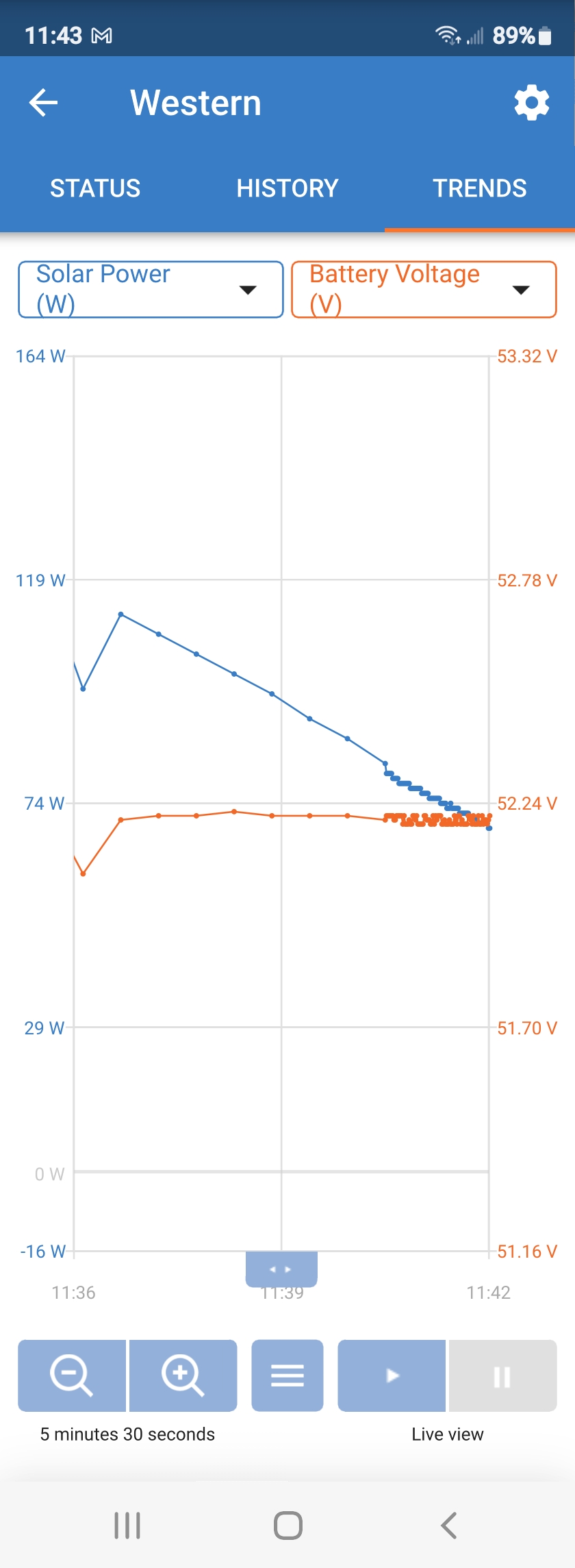
The battery is at 49.1V and I move the cart into bright sunlight. PV goes to 61.7V. A minute later, the MPPT system connects. Voltage drops to 59.3, Watts registers 180, and MPPT shows 3.6A. Within 15 minutes, the current tapers off to 1.0 A and wattage is 15-20. Battery voltage and PV is unchanged. Why? The battery needs voltage and is nowhere near absorption voltage. Why is the current backing off? The MPPT indicates bulk charging.

Confused...

MPPT Controllers
2 |3000

Up to 8 attachments (including images) can be used with a maximum of 190.8 MiB each and 286.6 MiB total.

6 Answers
Mike Dorsett avatar image
Mike Dorsett answered ·

there seem to be 2 main possibilities here:

first, check the temperature of the unit - if it is very hot, it will throttle back so as it doesn't melt itself.

second, a 10V head between the pv voltage and the battery voltage is barely adequate, and as your battery charges to 56V this will drop further. MPPT's generally need 5V difference to start, and >1v difference to run - so this is only a minor issue.

Other things to check (which you may already have done): Measure the battery voltage at the mppt connections and make sure that terminals are tight. What state is indicated by the MPPT is it still in bulk mode or has it gone to float? Also measure the PV voltage at the MPPT input.

1 comment
2 |3000

Up to 8 attachments (including images) can be used with a maximum of 190.8 MiB each and 286.6 MiB total.

kevgermany avatar image kevgermany ♦♦ commented ·
@stevenebraun


Could also be the panels getting hot.

But I don't understand the numbers. 1A on whichever side of the panels is about/over 50W.


0 Likes 0 ·
stevenebraun avatar image
stevenebraun answered ·

Someone needs to please explain this to me.

5v+ differential between PV and battery. 107F ambient temperature.Screenshot_20220830-114338.jpg


2 |3000

Up to 8 attachments (including images) can be used with a maximum of 190.8 MiB each and 286.6 MiB total.

klim8skeptic avatar image
klim8skeptic answered ·

Above the panels Vmp, there is less current (therefore power) available.

i-v-curve.jpg

Likewise solar panel specs are at a panel (cell) temp of 25c. (STC , standard test conditions)

If your panels are operating at an ambient temp of 40c, the cell temp is likely to be well above 60c. Cell temps can approach double ambient temperatures.

With an ambient temp of 41.7c, your cells could easily be at 75c. That is 50c above the panels STC.

With a Voc temp derating figure of -0.30%/c , that would equal a 15% lower Voc/Vmp.


i-v-curve.jpg (44.6 KiB)
2 |3000

Up to 8 attachments (including images) can be used with a maximum of 190.8 MiB each and 286.6 MiB total.

stevenebraun avatar image
stevenebraun answered ·

Nice theory but just now....

The ambient temperature is 109F. The temperature of the Victron 100 20 heat sink is 125.3F. The disconnected series PV array measures 63.7 VoC and 3.65 IsC. Battery voltage is 49.4 VDC with a connected PV array of 56.59 VDC. Current is 0.1A, watts is 8, and charge is Bulk.

Might be well above the 25C rating but does not explain this. I'm suspecting that my Li battery voltage at 56.8 with my PV VmP at 61.3 is incompatible with the Victron.

I previously used a Renogy RoverBoost but it would not handle the 15A current but it worked very well at 10A.

1 comment
2 |3000

Up to 8 attachments (including images) can be used with a maximum of 190.8 MiB each and 286.6 MiB total.

klim8skeptic avatar image klim8skeptic ♦ commented ·
What are the panel specs?
0 Likes 0 ·
stevenebraun avatar image
stevenebraun answered ·

Renogy RNG-100D-SS Gen3:
Voc: 24.3VDC x 3 = 72.9VDC
Vmp: 20.4 VDC x 3 = 61.2VDC
Isc: 5.21A
Imp: 4.91A

1 comment
2 |3000

Up to 8 attachments (including images) can be used with a maximum of 190.8 MiB each and 286.6 MiB total.

klim8skeptic avatar image klim8skeptic ♦ commented ·
0 Likes 0 ·
stevenebraun avatar image
stevenebraun answered ·

Thanks for the info. Already have it and used it before I purchased the 100/20. Still cannot figure out why the system won't work.

I reconfigured two of the three panels into a parallel 10A array, removed the 100/20, and connected to the Renogy RoverBoost yesterday. Immediately produced 190W and full charge for hours.

Something is not right in the 100/20.

BTW: I have two golf cart installations with 100/20 MPPT's doing the same thing.

5 comments
2 |3000

Up to 8 attachments (including images) can be used with a maximum of 190.8 MiB each and 286.6 MiB total.

klim8skeptic avatar image klim8skeptic ♦ commented ·
They are 2 different controllers, that are designed to operate in different ways.

The Renogy is designed to charge a 48v battery from a lower pv voltage. (15-40v)

The Victron is designed to charge a 48v battery from a higher pv voltage. (Vbatt +5v -100v)

For both controllers, they have a pv voltage input range they are designed to work in.

0 Likes 0 ·
stevenebraun avatar image stevenebraun klim8skeptic ♦ commented ·
Yes, I'm well aware of this. The reason for using the Victron was to utilize all 300W of power. Paralleled panels produce >15A and the RoverBoost can only handle 10A. Series connections produces 72 VoC and the RoverBoost can only handle 40V. So I'm limited to 200W.


The 100/20 can handle 75 VoC and 20 A. Match made in heaven. Except I can't get it to work.
0 Likes 0 ·
klim8skeptic avatar image klim8skeptic ♦ stevenebraun commented ·

You might want to read the Renogy power boost manual.

It can handle 600w of pv input@ 48V battery, and output 10a.

0 Likes 0 ·
stevenebraun avatar image stevenebraun klim8skeptic ♦ commented ·
The Renogy RoverBoost can handle 600W, no question. However, PV input is limited to 40V. I've got 72V with three panels and over 40V with two panels so I wire two panels parallel and I get 10A. Three panels in parallel is too many amps. Thus, I buy a Victron 100/20 and don't go with a boost style MPPT.


Not to be rude, but we are tap dancing here. What I am trying to determine is why the Victron 100/20 is acting the way it is. It starts off correctly and within 5 minutes tapers off to nothing. There is no heat problem, no wiring problems, brand new 135A 14S LiNMC battery, programmable BMS, and no errors on the Victron. I even have a Victron BMV-712 online and voltages match. There is well over 5VDC differential between PV and battery voltage at all times. I have tried every single parameter possible.

0 Likes 0 ·
klim8skeptic avatar image klim8skeptic ♦ stevenebraun commented ·
Read page 9 of the manual.

300w = 15a input

400w = 20a input

500w = 25a input

600w = 30a input

0 Likes 0 ·