question

jerrad-roberts avatar image
jerrad-roberts asked

Review my wiring

rv-drawing.jpg

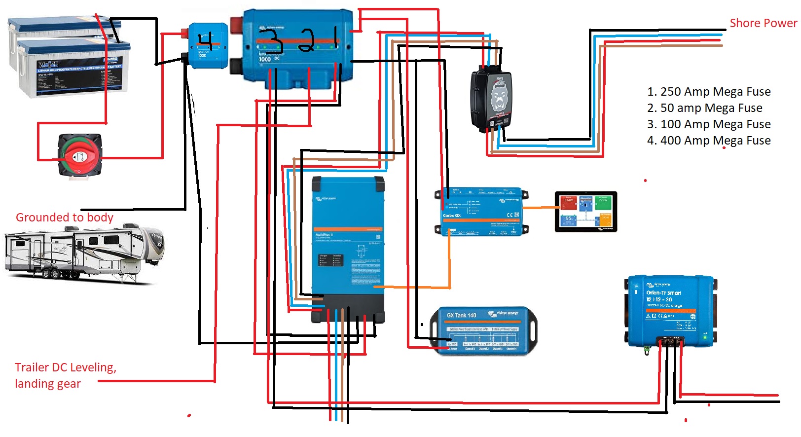
This is my wiring. Any critiques or anything would be greatly appreciated it. From the Batteries are 200 ah a piece. I ran 2 gauge wire from the batteries to shut off and then to the shunt. From the shunt to the inverter is 1 gauge. The DC to DC charge connects to a quick disconnect ultimately going straight to my alternator of my truck and is ran with 6 gauge wire. I turned this all on and tried to run it off the batteries and as soon as the AC kicked on it blew the 250 amp fuse. Just trying to figure out my mistake. Thank you.

wiring diagram
rv-drawing.jpg (298.9 KiB)
2 |3000

Up to 8 attachments (including images) can be used with a maximum of 190.8 MiB each and 286.6 MiB total.

3 Answers
jerrad-roberts avatar image
jerrad-roberts answered ·

Looking at other diagrams, does no one use the little ground bolt on the Multiplus ii? Everything was working find and then I upgraded the batteries and noticed I forgot that ground and not sure if that is what caused it to blow or what.


4 comments
2 |3000

Up to 8 attachments (including images) can be used with a maximum of 190.8 MiB each and 286.6 MiB total.

klim8skeptic avatar image klim8skeptic ♦ commented ·
12v battery? What model inverter?
0 Likes 0 ·
jerrad-roberts avatar image jerrad-roberts klim8skeptic ♦ commented ·
Yes it is 12 v batteries with the multiplus ii 12v/3000
0 Likes 0 ·
tom4x avatar image tom4x commented ·

Your diagram does not show the terminals, so it's hard to guess that this one black line is the grounding and not the battery connection. Of course the chassis of the MP II should be grounded, that's correct.

0 Likes 0 ·
jerrad-roberts avatar image jerrad-roberts tom4x commented ·

so the inverter ground needs to go to the negative bus bar not the shunt?

0 Likes 0 ·
Kevin Windrem avatar image
Kevin Windrem answered ·

If the inverter is the 3000 VA Multi II 120x2 then the DC fuse should be 400 amps not 250. Also the wires should be TWO 1/0 AWG not ONE 1 AWG. Battery wires should be of similar or larger also. Those are according to the manual.

Although undersized, a MODEST load on the inverter should not blow the fuse. But if you are drawing anywhere close to the inverter's rated output a 250 amp fuse might blow. 3000 watts at 12 volts is 250 amps so the fuse size should be larger to handle surges.

If you have a large AC load or a short circuit in the output wiring then this could easily blow the fuse.

NOTHING except the battery negative should connect to the battery side of the shunt. ALL other negative wiring should connect to the load side of the shunt. That includes all safety grounding and chassis grounding.

1 comment
2 |3000

Up to 8 attachments (including images) can be used with a maximum of 190.8 MiB each and 286.6 MiB total.

jerrad-roberts avatar image jerrad-roberts commented ·
So should it be 2 x 400 amp fuses with 2 x 1/0 wires or 2 x 200 to make a total of 400 amps since it is 2 wires? And when you say the battery wires does that include the wires connecting the batteries together or just the wires that connect the shunt to the first battery in the group? Thanks for the advice.
0 Likes 0 ·
rikhf avatar image
rikhf answered ·

Why is the minus lead from the battery (on the shunt side) going direct to the inverter and not via the distributor?


2 comments
2 |3000

Up to 8 attachments (including images) can be used with a maximum of 190.8 MiB each and 286.6 MiB total.

tom4x avatar image tom4x commented ·
I guess that should be the grounding of the chassis according to the answer by the OP himself above.
0 Likes 0 ·
jerrad-roberts avatar image jerrad-roberts commented ·
yes that is the ground going to the chasis that I need to move to the distributor side.
0 Likes 0 ·

Related Resources

Additional resources still need to be added for this topic