Anyone know if the Victron MPPT solar charge controllers create RF Interference when used with HAM radio operations?
asked
RF Interference and mppt charge controller
I´ve got a BIG RFI issue with a 150/60 MPPT.
It´s really noisy from HF up to ~100 MHz, but no problems at all at 144 MHz.
Also using a USB-dongle for monitoring and it´s really noisy and the interference is moving around mostly at ~430 MHz.
This interference appears as a 50 kHz wide strong signal, but after some ferrites it works better. I´ll also try to apply some CU-tape, maybe it will solve my issue.
Hello to all
I do ham radio and have a 7kw Solar home ( sunnyboy 7.0 ) wired like this
From a QST write up on RFI from PV(link)
fast forward to 2021
Doing a lot of backyard small solar projects this pandemic summer
and working on solving the RFI and radio static from the backyard system
I use this to charge a 20Ah battery and power a USB hub , small computer and my smaller ham radio's.
I came up with some RFI control devices I would like to share info on.
If you are a ham , look me up on qrz.com.
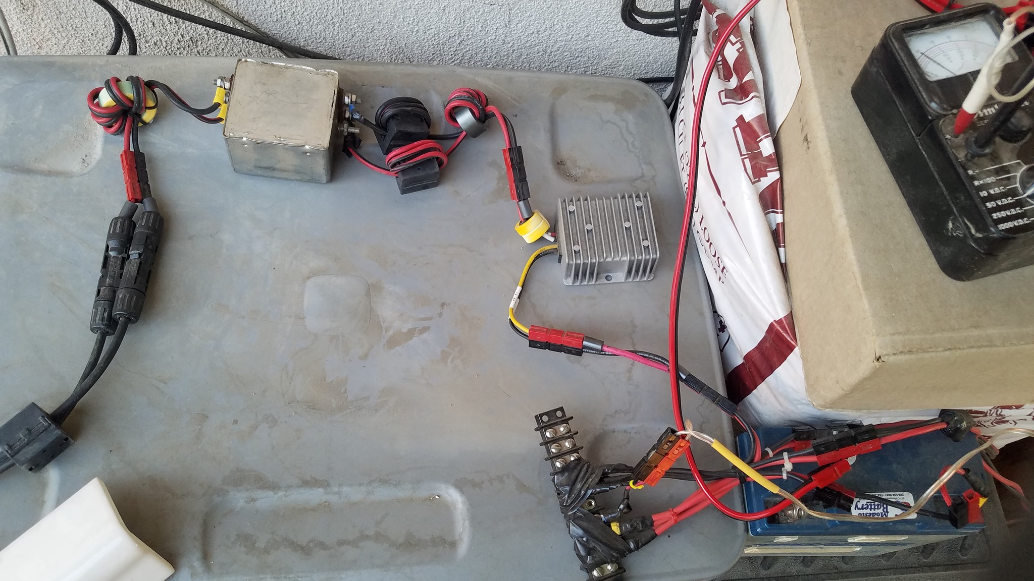
below is the test setup , I have been monitoring the system with a 'Tiny SA' device ($60)
this lets you see the radio spectrum real time , a great tool for hunting down RFI.
I have found that AC line filters can be used to suppress the high frequency noise
from the charge controller going to the PV array , also very important to run the wires as a
twisted pair (- and + ) together to cancel out the noise more , running only a single wire
to the PV array will make it a great loop antenna to transmit the noise a lot more.
FEEDBACK WELCOME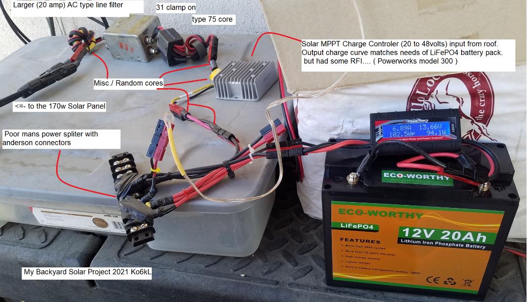
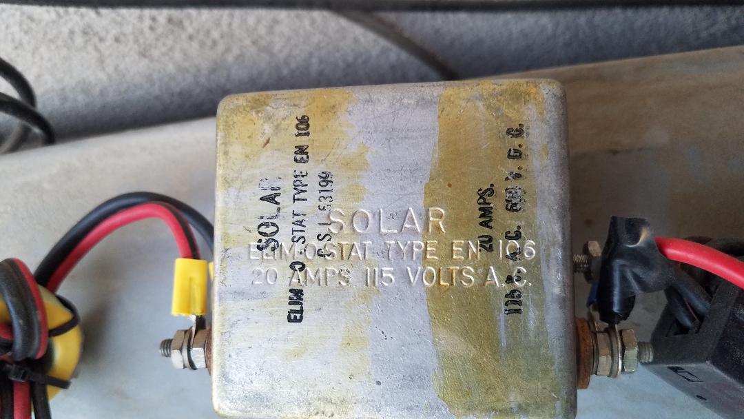
Yea it listed as AC but will pass the DC just fine ( from my junk box) , watch your AMP specs.
to do all the testing I put anderson powerpole connectors on everything.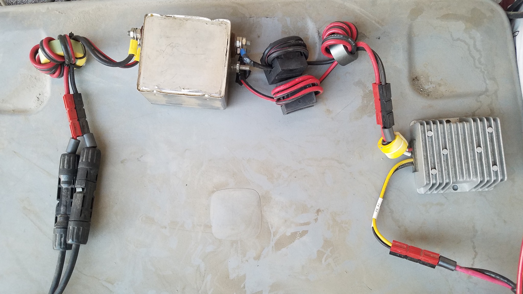
last build added some more of the used AC line filters pulled from old power supply's.
Also some green anderson pole connectors tie into the nearby earth ground rod
( Use the shortest path to the auto frame if your doing a RV )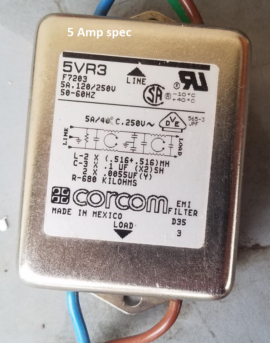 a little light on the amp spec on the output side but working fine
added a large type 43 fairitechoke core at mppt controller
needs more turns on the core to work better ( should be inside every device IMO)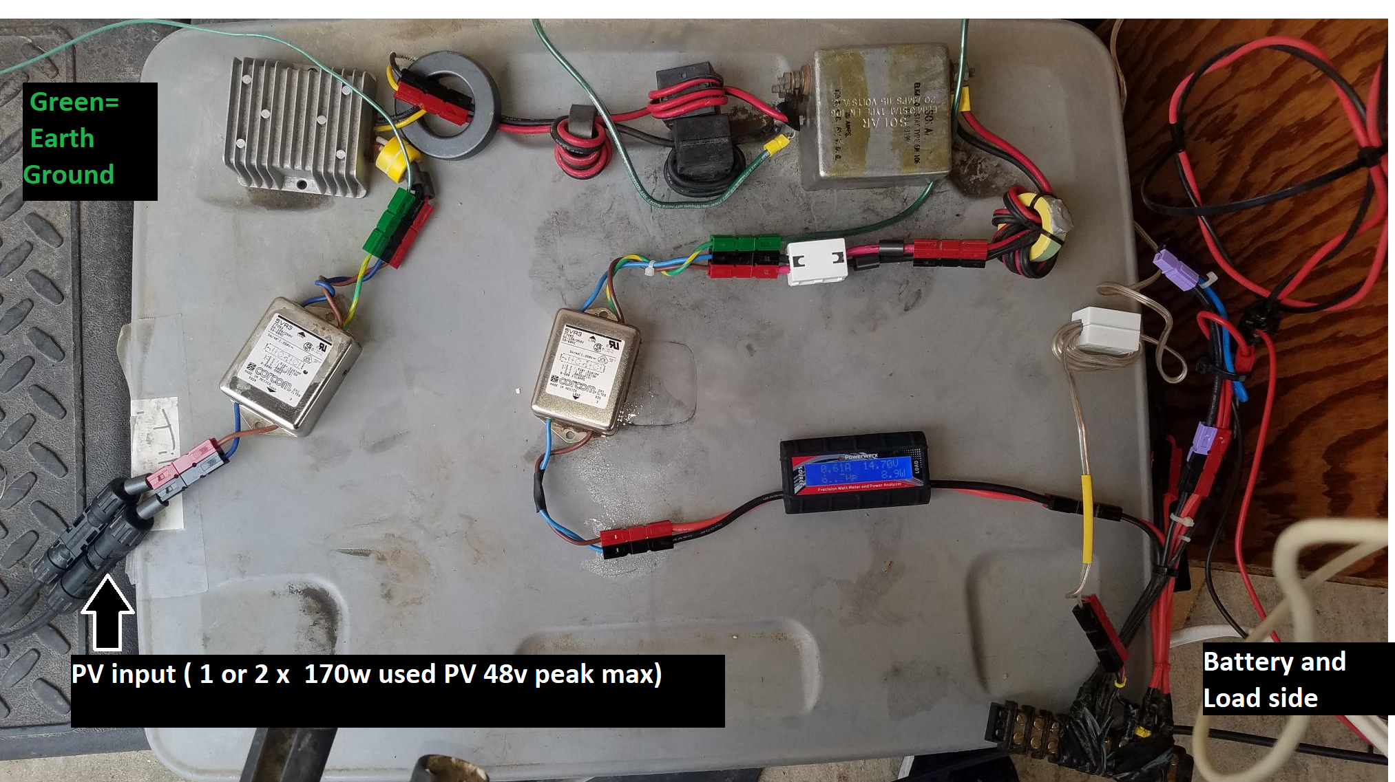
Kind regards
Living static free in Sunny California.
I have resolved this issue. The MPPT switching of mosfets can create RF if DC and AC earths are not correct. Put simply the switching of the Mosfets to convert a high voltage to a lower voltage generates an Alternating current in the solar panel circuit. Below is a method of stopping these currents becoming an RF issue
Really important The solar panel Positive and Negative wires are run next to each other with ABSOLUTELY NO earth connections in the solar panel wiring circuit. The frame of the solar panel is a separate safety earth.
The main Earth in the circuit is at the Negative battery Terminal. But if the cable length from MPPT is say 5m to battery and 1M to earth then even though there is a low resistance in the cable it can create an RF antenna of 6M. The simple work around is to move the MPPT charger so this antenna is very very short. say 100mm cable to earth then a short cable from the earth piont to the battery . Both cables need fuses.
Not sure of different country wire standard but if you have to have a long cable + earth for the DC circuit then try a short bypass cable for the RF to earth . Think it should have a dc blocking by-pass capacitor selected for the frequency your trying to reduce inference. worked for me.
One more issue is to measure the DC voltage between Solar panel Negative and Positive outputs with respect to the Solar panel frame earth. There should be no voltage with respect to earth on either Try open circuit first then MPPT device on load.
A DC voltage between the solar panel frame earth and say the Negative of asolar panel is a real problem . What is happening is the panel wiring insulation breaks down inside the solar panel and a resistamce conection to is occuring to the Solar pannel frame . This is why it has to be earthed for safety. This is a common failure.
The panel fault must be removed.
The simple way is to make an educated guess use a proportion method.
4 x 30 volt open circuit voltage solar panels in series produce 120 volts. If one of the solar panels is leaking curent to the solar panel frame and you measure 55 volts then the fault is nearly half way in the circuit = Number 2 panel . Do not try and measure the current if you have a voltage. you will blow your meter up.
The reason for the RF noise in this situation is that an earth has been made by the faulty panel to earth part way in the Solar panel circuit
Thus the currents are not equal in Positive and Negative be wires. Oscillations occurs and depending on the resistance of the leakage to ground you have an antenna for 1 or many RF channels.
Hope this helps.
Apart from the microcontroller's CPU clock I can't think of any other sources of RF in any such device. It's all DC with an MPPT sweep every now and then, as far as I can imagine.
Have a browse on the Victron website, there are a load of certificates for each product. I'm not a HAM, so I don't know what applicable standards or certificates you a looking for.
I'm no expert, but I would also expect to see some DC/DC switched circuitry inside the MPPT. Switched power supply modules can produce some interference, mainly in the 100-300 kHz range, but some harmonics can go up to the lower MHz region of spectrum, depending on specific solution and the filtering or eventual screening used.
Interesting! This may explain why I am experiencing occasional strong interference when listening to my radio at medium wave frequencies (570 kHz) in the morning. The interfering signal starts suddenly and then slowly sweeps up in frequency - probably as the sun rises higher and the MPPT re-adjusts to the solar panel output.
Most DC-DC converters (that perform the MPPT function) operate in the 150kHz - to 1.5MHz range, but the RF noise could be a harmonic of this frequency. If this is coupling back into the cables from the solar panels, this could act as a huge antenna, especially at medium wave frequencies.
I have the Bluesolar MPPT 150/70 Tr connected to a 52V LiFePO4 battery pack.
Multiple users have reported RF interferrence on the AIS VHF bands (161.975 and 162.025). I definitely have the issue and have repeatable tests showing the Victron controllers are the culprit.
Yes the MPPT causes massive HF band noise. I have to switch off our 100/50 MPPT using the Bluetooth control if I want to use the HF radio.
As noted charge controllers run in the 100KHz to 150KHz range. However, that is NOT where the RFI comes from. The charge controller FETs are switched on to full power and switched off to zero during that cycle. It is not linear. The problem is the switching time between on and off. At a 100kHz operating frequency, the FET is switching on, then off in 10us (1/100KHz). To be 98% efficient means the switching time must be less then 2% of the cycle as the bulk of power losses are during the switch time. This means the FET must turn on and off in 2% of the 10us or 200ns. This is where the REAL RF power is. Going from zero to 30 amps and back to 0 again in less than 200ns. That edge will generate a 5MHz signal and ALL its harmonics!
Without filters on the input (solar side) and output (battery side) that rf will go out on all wires. The more wire between battery, ground solar panels and FETS the more RF will propagate into the air. All installations will have some kind of long runs so something else is needed to kill the RF BEFORE it gets to the wires. Simple ferrite beads won't kill that much rfi. Really ferrite beads are useful to keep rfi out of things like your bow thruster contollers or battery monitors. For real power rfi you need to build common mode filters that can handle high dc currents. Non trivial but possible. Also, the filters and controller should be enclosed in a faraday box.
It may be easier to shut of the charge controller while operating HF!
I have something to add. I think the RF interference is coming from can bus communication somehow. I had a MPPT 150/85 - MC4 for a couple years and it failed one day and I never had any radio interference from it. Victron was great at sending a replacement but they replaced it with a MPPT 150/85 - TR VE.Can. I think the only differance is the can bus communication and the interference sounds like communication or music He is a video of it:
https://youtu.be/4BPO3PQOo5w
Perhaps Victron could add a way in a firmware update to turn off the can bus communication?
Well done! There is another reason to wrap BOTH the positive and negative leads together on the toroid: If you wrapped only one (positive or negative) the DC current would saturate the ferrite core, making it ineffective. With both positive and negative leads wrapped together, the algebraic sum of the currents is zero. I always leave a good gap between the first input wrap and the last output wrap to avoid capacitive coupling.
any ideas from victron? i think lots of HAMs and CBs have this problem.
i also have to switch off my 2 mppt 150/85 TR VE.Can when i want to use my CB or HAM radio.
please find a (firmware) solution for this realy annoying problem.
with 30A and 70A mppts this problem was not as bad as with my newest 85A MPPT.
Has anybody looked into shielding their devices with a Faraday Cage to keep the RF from getting out and interfering with HAM operations?
I imagine it would be challenging given all the cables (ie antenna) running into and out of the devices, but maybe?
I had 57-59 interfernce on both 80m and 40m from my 24V Multiplus and 100/50 MPPT. My solution was:
1. Put one ferritring on the +/- cable from the solarpanel (It has to be one ring on both +/- cable.
2. Good grounding of the multipluss !
Result back to normal qrm of 52-53.