question

rns avatar image
rns asked

How to use the Multiplus II current sense port

On the multiplus II there is a current sense port. I can't find how to use it.

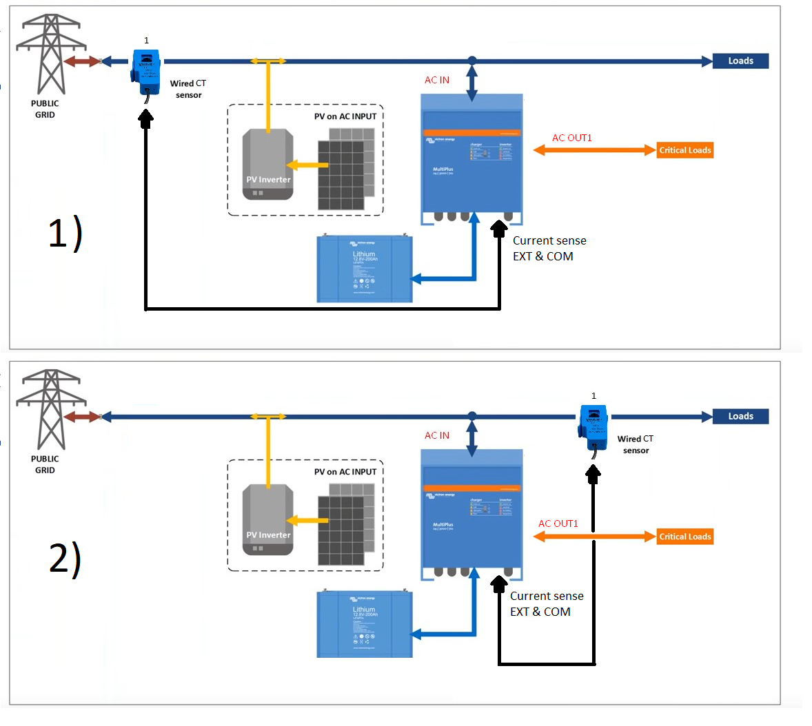
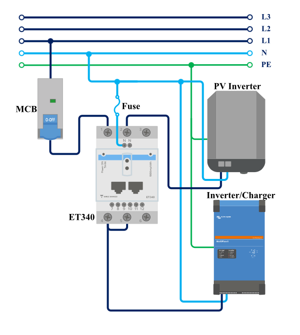
In the online training I see the current sensor is connected to the temperature sensor or the aux ports an that is also what the ac assistant is giving as options.


How to I use the current sense port ? I have a sct013 100A 50mA current sensor from my own energy monitoring project also from yhdc as the one victron uses. Would like to reuse that sensor.

Who can help me read that value ?

Multiplus-II
10 comments
2 |3000

Up to 8 attachments (including images) can be used with a maximum of 190.8 MiB each and 286.6 MiB total.

rns avatar image rns commented ·

I'm still stuck on this one, who can help me

0 Likes 0 ·
klim8skeptic avatar image klim8skeptic ♦ rns commented ·

You have looked at the Datasheet?

ESS quick installation guide.

Current Transformer 100A:50mA for MultiPlus-II / MultiGrid-II to implement PowerControl and PowerAssist and to optimize self-consumption with external current sensing. See MultiPlus-II datasheet for more details.

Current transformer. <<Link

0 Likes 0 ·
rns avatar image rns klim8skeptic ♦ commented ·
I have exactly the same current sensor form another project. I did connect it and activated it in the configuration but now I want to know how I can get that value visible.
0 Likes 0 ·
cooleco avatar image cooleco commented ·

Hi there,

This thread has helped a little bit but I still need a clarification to ejrossouw 's comment.

If I have a PV inverter + grid on the AC-in port, and I wish to see logical data for the Grid values (and Loads). The plan is to use ESS to set up self consumption and see correct data.

1) Should I connect the CT to the Grid main feed of the house
2) Connect the CT before the loads paralleling everything on Grid side?

Number 1 option makes sense to me. However then I cannot see a way to read the paralleling loads. (Unless its calculated?)

Many thanks in advance!

Also in my case I am able to read the PV production via PV inverter (SMA) sending the data using the Modbus TCP server (which the cerbo is able to read). See third picture below.

Please see the image:
1707270672424.png


VRM:
1707271052107.png

0 Likes 0 ·
1707270672424.png (388.6 KiB)
1707271052107.png (80.7 KiB)
ejrossouw avatar image ejrossouw cooleco commented ·

The CT is connected as per 1 and shown in the ESS manual, just using an ET112 as opposed to CT. You will require a GX device in order to use ESS.

0 Likes 0 ·
cooleco avatar image cooleco ejrossouw commented ·

Thank you for the reply @ejrossouw

I have a Cerbo GX in the installation.

There is still not perfect / clear documentation on this ESS implementation and wiring released by Victron (IMHO).

The words used by people in this thread are somewhat vague, others have mentioned words "current sensor" - which logically could be a CT (but following links say it is not).
Industry definitions for "Smartmeter/energy meter (normally measuring Volt,Amp, Watt)" is different to a "current sensor/current transformer (only measuring amps)".

The Victron "current sensor" product is only made to measure PV Inverter power connected to the AC input or output of a Multi or Quattro. They should have named the product Victron PV sensor or Victron PV smartmeter (because the output is digital output).

Then the actual "current transformer" product is only made to measure grid input to premises to avoid grid-feed in - According to multiplus 2 datasheet. They should have named this product Victron Grid Sensor or Victron Grid CT (because the output is analog output). This product or feature SHOULD ideally be able to do what a smartmeter/energy meter does on the grid input side, yet it does not. Why?

So, using a CT (current transformer such as the blue YHDC) plugged into the current sense INT and COM ports will not be sufficient for ESS? The links I posted have contradicting info. Multiplus 2 datasheet says the CT is to optimise self-consumption and, if required, to prevent grid feed.

A smartmeter will output digital output via rs485/VECan and must be connected to the GX. The installation of a smartmeter/energymeter like the ET112 (shunt) is very intrusive and not easy for all customers. Installing a CT is much easier.


0 Likes 0 ·
cooleco avatar image cooleco cooleco commented ·

I do not want to install the ET112 unless I need it for ESS. I read then this in the ESS documentation :

Grid Meter (optional)
An Energy Meter can be installed in the main distribution panel between the grid and the installation for a full or partial grid-parallel installation.
A grid meter is not required where there is no AC renewable-energy source(s) and also no AC load(s) present on the input side of the Multi/Quattro system (i.e. where all such sources and loads are on the output side of the Multi/Quattro system).


If there is any AC renewable energy source or any AC load between the grid connection point and the input side of the Multi/Quattro system, incorrect results will be calculated and recorded by the GX unless a grid meter is installed and enabled.
In particular, without a grid meter:
• When renewable energy is being provided on the input side, the grid value will be wrong (too low/negative); and Comment-- BUT if we use TCP Modbus server or current sensor then the PV production would be known!
• The AC Load value shown will be too low (and will show zero where there is a surplus of renewable energy).
Both issues are resolved by installing a grid meter.


Also having to find software setting definitions from community pages is not ideal, eg like this or this.

0 Likes 0 ·
ejrossouw avatar image ejrossouw cooleco commented ·

@cooleco The CT is an extension of the MP-II's internal metering and can be used for ESS as I already pointed out. (It has a dedicated port.) You can otherwise use an "external" ET112 energy meter. The choice is yours. If your PV inverter cannot communicate with the Cerbo and you want to diplay it's production, you can install an additional ET112 or even ET340 as below. 1707380278360.png

Typically these points are discussed with your dealer who should be able to answer your questions at the system design stage. Victron systems are typically installed by qualified professionals and while documentation is comprehensive, it is not intended as in-depth training/installation material on products.

0 Likes 0 ·
1707380278360.png (52.8 KiB)
cooleco avatar image cooleco ejrossouw commented ·

Thank you @ejrossouw

We may test out the CT solution as it is easier to implement.
Do you have any reference to documentation or any links to share that says the current transformer is OK for ESS?
Only document I found was the Multiplus 2 datasheet:
https://www.victronenergy.com/upload/documents/Datasheet-MultiPlus-II-inverter-charger-EN.pdf
Cheers


0 Likes 0 ·
ejrossouw avatar image ejrossouw cooleco commented ·
I personally use one as do many of my customers ;)
0 Likes 0 ·
6 Answers
ejrossouw avatar image
ejrossouw answered ·

You plug the current sensor into its port on the MP and enable it on the MP using VE.configure by ticking the enable external meter box.


1 comment
2 |3000

Up to 8 attachments (including images) can be used with a maximum of 190.8 MiB each and 286.6 MiB total.

rns avatar image rns commented ·

Ok did that but where do I see the value now ?

0 Likes 0 ·
ejrossouw avatar image
ejrossouw answered ·

It is the value shown for the MP in VE.Config, VE.bus monitor, rconsole and in the VRM portal. Not sure what else you expect. Underlined in red.1652515442034.png


1652515442034.png (105.5 KiB)
1 comment
2 |3000

Up to 8 attachments (including images) can be used with a maximum of 190.8 MiB each and 286.6 MiB total.

rns avatar image rns commented ·

I have a shunt so that one is measuring it already. I was hoping I could use this current sensor as an extra sensor to measure a load or grid feedback.

So with the shunt this doesn't make sense to use this sensor correct ?

0 Likes 0 ·
ejrossouw avatar image
ejrossouw answered ·

The shunt gives you DC view, while CT an AC. It very much allows the MP to see AC loads "in front" of it when connected grid parallel to e.g. household loads that is not connected to ACOUT. If there are no loads parallel to the MP it will not add much value as the MP already measures what passes through it.

2 comments
2 |3000

Up to 8 attachments (including images) can be used with a maximum of 190.8 MiB each and 286.6 MiB total.

rns avatar image rns commented ·
Hi now you confused me. In the screenshots it was indeed DC current so ist not comming from this current sensor.

In your last post this looks to be what I want but where do I see that value when I connect the current sensor.

In my situation the multiplus is not AC IN connected so is that maybe an issue ?

0 Likes 0 ·
rarehyde avatar image rarehyde rns commented ·
I have the same situation as you. Got the same current sensor. Not sure where to activate it in ve configure. Send a screenshot if possible to show where.
Did you get your situation sorted out?
0 Likes 0 ·
ejrossouw avatar image
ejrossouw answered ·

My apologies. My screenshots were wrongly showing the battery value. The CT value is in the grid box.368eb0af-ed1b-4e1c-8c43-7e74b05f48ad.jpeg


1 comment
2 |3000

Up to 8 attachments (including images) can be used with a maximum of 190.8 MiB each and 286.6 MiB total.

rns avatar image rns commented ·
Ok thanks, I have no grid connection on AC1 IN on the multiplus but I did connecte the current sensor. I have no values on Grid. Do I need to activate something in the config aside the checkbox for the external current sensor ?
0 Likes 0 ·
1234enough avatar image
1234enough answered ·

Feel the need is to read up on the excellent victron manuals and to grasp the basics.

External sensor 3.5mm jack socket simply disconnects (when you plug an external ct into it)the MP internal CT clamp ( measuring AC current passing through the MP) and transfers the measurement point to where ever you place the CT clamp, this is displayed as Grid /shore or whichever you set the MP as.

For ESS the point at which you place the CT is usually grid supply coming into the system, then set grid set point( amount of electricity you wish to flow into system from grid ) and ESS will then try to maintain this set point (subject to many other set- able parameters).

2 |3000

Up to 8 attachments (including images) can be used with a maximum of 190.8 MiB each and 286.6 MiB total.

farmeroz avatar image
farmeroz answered ·

Really this is another question, but fits with this thread.

If you have nothing else connected to grid, that is batteries and PV all power the 48VDC bus directly, then there is no need for a CT at all as the Multi-2/Quattro-2 will automatically disconnect on mains failure.

PS All loads are on UPS line. Exporting surplus PV to grid is however an aim.

2 comments
2 |3000

Up to 8 attachments (including images) can be used with a maximum of 190.8 MiB each and 286.6 MiB total.

Craig Chamberlain avatar image Craig Chamberlain commented ·
Yes, that's my understanding at least. If all loads are on AC-Out1 or AC-Out2 then you don't need an external CT or grid meter. The MP-2 has an internal CT and therefore it can measure or derive input, output and inverter power levels. In my case I have loads upstream of AC-In such as EV charger, electric shower and range cooker which are too heavy for the MP-2 to supply in a grid loss scenario so I have to use a grid meter.

HTH

0 Likes 0 ·
farmeroz avatar image farmeroz Craig Chamberlain commented ·
Interesting. Is that actually true? Even if you have dumb (ie just consuming devices) stuff 'direct from grid' that will not affect ACin at the MP from detecting mains failure so a CT should not be required at incoming. None of these devices can generate power to fool the MP into thinking the grid is still on.
0 Likes 0 ·