question

echidna avatar image
echidna asked

Inverter DC ripple voltage specification

I'm trying to get some clarity on the DC ripple specifications relating to Victron inverter/chargers. There is contradictory data in different places, and a lack of clarity, not to mention some technical inaccuracies.


Specifically, what are the allowable ripple levels for 12V, 24V and 48V inverters for

(a) the ripple warning

(b) ripple shutdown

and are these numbers RMS or peak-to-peak values?


If I look at https://www.victronenergy.com/live/_media/ve.bus:4._ripple_in_a_ac_battery_system.pdf it shows a graph of ripple voltage, indicating peak-to-peak measurement with the magnitude labeled "Ripple".It states that the ripple warning occurs at 1.2V and shutdown at 1.5V. No mention is made of the battery voltage, but FWIW the graph is shown adjacent to a picture of a 24V Multiplus.


If I look at the manual https://www.victronenergy.com/upload/documents/Manual-Quattro-5k-8k-10k-15K-100-100A-230V-(firmware-xxxx4xx)-EN-NL-FR-DE-ES-SE-IT.pdf it states under Section 7.1 General Error Indications that for the ripple warning, the "Ripple voltage on the DC connection exceeds 1,5Vrms". Again, no mention is made of whether this depends on battery voltage.


Finally, in the Wiring Unlimited book https://www.victronenergy.com/upload/documents/Wiring-Unlimited-EN.pdf there is a detailed table listing the following values as a function of battery voltage (shown here in parentheses after the ripple value):

Ripple pre-alarm: 1.5V (12V), 2,25V (24V), 3V (48V)

Full ripple alarm: 2.5V (12V), 3.75V (24V, 5V (48V)

Again, a diagram shows the ripple measured as peak-to-peak, but the actual specification does not say peak-to-peak or RMS.

For a roughly sinusoidal waveform (as the ripple voltage will normally be in practice due to the filtering effect to the inverter DC input capacitors), there is a factor of 2,8 difference between peak-to-peak and RMS!


In a couple of places, the use of an AC multimeter is suggested to measure ripple. Such instruments will normally report the RMS value of the waveform, but if the waveform is significantly non-sinusoidal, the reading will vary depending on whether the meter is true RMS or average-modulus responding.


So, what are the correct values for the ripple pre-alarm and the full alarm (shutdown) as a function of DC battery voltage, and are they RMS or peak-to-peak?

What does the VE Configure application report as Udc ripple? RMS or peak-to-peak?


MultiPlus Quattro Inverter Charger
2 |3000

Up to 8 attachments (including images) can be used with a maximum of 190.8 MiB each and 286.6 MiB total.

19 Answers
Margreet Leeftink (Victron Energy Staff) avatar image
Margreet Leeftink (Victron Energy Staff) answered ·

Here is the definite answer and has been verified by the Victron Software engineer.

The ripple is measured in RMS. The ripple values are as follows:

For the MultiCompact inverter/chargers (regardless of Vdc value):

1.5V 20 min
2.5V 3 sec
0.8V charge regulation level

For all other products:

12Vdc models

1.5V 20 min
2.5V 3 sec
1.4V charge regulation level

24Vdc models

2.25V 20 min
3.75V 3 sec
2.1V charge regulation level

48Vdc models

3V 20 min
5V 3 sec
2.8V charge regulation level

2 |3000

Up to 8 attachments (including images) can be used with a maximum of 190.8 MiB each and 286.6 MiB total.

Alexandra avatar image
Alexandra answered ·

@echidna

The documents you refer to are aimed at non technical people, not electronic professionals so do explain in non jargon and formula terms the issues that cause DC ripple and acceptable limits to them. And also in simple terms how to correct the issue. I would not say they have contradictory data.

The relationship of VIR is important in electronics, so obviously the voltage of the system and current drawn in the system would affect the resistance and so the bad ripple value would be different for each system. The differences are laid out in wiring unlimited as you saw.

Since the Victron is not a measuring instrument, nor claims to be one, assume it is peak to peak since it is not a calibrated instrument? If you assume RMS it suggests there is a larger peak and therefore more tolerance (which in my mind is a bad thing), as ripple adds losses, noise heat and a variety of other very bad consequences, as I am sure you are aware.

All I can say if your system is getting 5V on 48V alarms (yikes), whether RMS or peak voltage differences; you have bigger issues than wondering if peak to peak or RMS is being used to determine the limits.

2 |3000

Up to 8 attachments (including images) can be used with a maximum of 190.8 MiB each and 286.6 MiB total.

echidna avatar image
echidna answered ·

Alexandra, I'm afraid your response is not at all helpful.

The contradictions and confusion in Victron's published data which I referenced are obvious from my post. While these documents may have been written for a lay audience (although I would say the Quattro manual I quoted is more of a formal technical document, especially the specifications sections), they were presumably written by or at least (should have been) vetted by a Victron engineer.

The difference between peak-to-peak and RMS values is a major one: it needs to be clarified whether specified values are RMS or peak-to-peak. You can't whitewash over this distinction.


Your response also suggests some basic misunderstandings about "ripple" issues. You need to distinguish ripple current from ripple voltage. The current drawn from the DC input by a full-bridge PWM converter has the classic "full-wave rectified sine wave" form (after averaging over the PWM switching frequency), assuming a linear load on the AC output of the converter (sine wave AC output current).

The AC component of the current at the DC input to the bridge constitutes the "ripple" current drawn by the converter. You can’t get rid of that ripple current, although you can reduce the ripple voltage it causes by appropriate measures. In the situations we are dealing with, that current has two places to go: through the capacitors across the DC input to the bridge, and through the battery. The ripple current has a fundamental frequency of 100Hz for a 50Hz converter or 120Hz for a 60Hz converter, with significant harmonic content due to its non-sinusoidal waveform.

With a large, low-impedance battery bank, connected with low-impedance wiring to the converter, a large part, ideally the bulk of the lower frequency components of the ripple current will flow through the battery, depending on its specific characteristics. At higher frequencies, the decreasing impedance of the input capacitors (limited by their ESR) will lead to a greater proportion of the ripple going through the capacitors. Those capacitors also carry virtually all of the PWM switching frequency current (~20kHz for Victron, I believe).

Having a large, lower frequency ripple current going through the capacitors can cause excessive heating of them and lead to a reduction in life. You can tell roughly how much current is going through those capacitors by looking at the ripple voltage at the converter DC terminals. Thus a large ripple voltage at that point is undesirable. High ripple voltage at the converter DC terminals can also cause issues for the PWM control loop.

But in reducing the wiring impedance between the battery and the converter, and in reducing battery impedance by employing a large bank with good internal wiring, you are simply diverting ripple current from the input capacitors to the battery, and in fact increasing the ripple current carried by the battery and the wiring between the battery and converter.

In this regard, note the following statement in the Wiring Unlimited book: “The batteries will age prematurely, each ripple acts as a mini cycle of the battery.” This is wrong in a number of ways, but most importantly in that the recommendations in that document to “reduce ripple” will actually increase the ripple current through the batteries!


2 comments
2 |3000

Up to 8 attachments (including images) can be used with a maximum of 190.8 MiB each and 286.6 MiB total.

Alexandra avatar image Alexandra ♦ commented ·

@echidna

You could install a Victron, put undersized DC cable on it (break all the rules in wiring unlimited), set up oscilloscope and make the system shutdown while taking readings. Then you will have a definitive answer.

Use lower voltage system it is easier to get DC ripple there as there are higher current draw and larger voltage drops and easier to overload the system to shutdown.

Then set up as recommended and do the same experiment again.

3rd time set up with oversized DC cable set up and do it again.

Of course measure with the Meter like an average person would and also do your more complex tests of course. I do have one question though. how would you measure ripple current in a battery?

0 Likes 0 ·
shaneyake avatar image shaneyake commented ·
@echidna Can you maybe explain what you are trying to do? If you install components in the recommended way ripple is normally a non-issue. Even at 200kVA+
0 Likes 0 ·
echidna avatar image
echidna answered ·

Alexandra: I don't see why I should have to effectively reverse-engineer Victron's specifications for ripple tolerance.

Measuring battery ripple current could be done with a shunt, Hall-effect monitor, or if you don't need to see the DC component of the current, with an AC current transformer or Rogowski coil.

Shaneyake - you seem to be missing my point. Regarding ripple effects, Victron have inconsistent, confusing, incomplete, and poorly specified data (not to mention incorrect information) in various places (see my original post). They should fix this and state the allowed ripple voltages clearly (RMS, peak-to-peak, or whatever), and with regard to the inverter nominal battery voltage, and correct some technical inaccuracies.

Because of an investigation of different manufacturer's equipment I was involved in, I took the trouble to read all I could find on Victron's web site regarding ripple tolerance, etc. and came away with confusion. A good engineer (working for Victron) would take this stuff and sort it out.

2 |3000

Up to 8 attachments (including images) can be used with a maximum of 190.8 MiB each and 286.6 MiB total.

echidna avatar image
echidna answered ·

Margreet - thank you for clarifying that information. I have two follow-up questions.

I assume that the times mentioned in your post (20 min and 3 sec) are the times that can elapse at the specified ripple level before a warning or a shutdown (respectively) occurs. Is that correct?

Also, what is the definition of "charge regulation level"?

2 |3000

Up to 8 attachments (including images) can be used with a maximum of 190.8 MiB each and 286.6 MiB total.

echidna avatar image
echidna answered ·

Shaneyake - I meant to add something to my response to you yesterday: you referred to a 200kVA+ level. Such a high-power system would be invariably be implemented as a three-phase system. This completely changes the ripple situation.

A standard 6-pulse three-phase converter has a much lower ripple current at the bridge DC terminals. For such a converter, the peak-peak current ripple at the DC bridge terminals is about 14% of the average DC current (assuming a balanced, linear 3-phase AC load).

Compare this with a single phase system where the peak-peak ripple current is about 1.6 times the average DC current.

Thus ripple effects are much less in a three-phase system vs. a single phase system

Furthermore, the fundamental ripple frequency is now 360Hz in a 60Hz system, instead of 120Hz, so the reactance of the DC input capacitors is reduced by a factor of 3 relative to the single-phase system.

Now Victron implement three-phase systems as interconnected single-phase converters. So the ripple performance will depend to some extend on how large the impedance (resistance plus inductance) of the DC interconnects is. But with good layout, performance should be close to what is achieved in an integrated three-phase bridge design.

2 |3000

Up to 8 attachments (including images) can be used with a maximum of 190.8 MiB each and 286.6 MiB total.

fabianm avatar image
fabianm answered ·

I got a Multiplus 2, 48V / 3kVA last week in order to use it for ESS. As I was never using Victron products before, so I bought only Multiplus (together with Cerbo GX) for now and a cheap 48V 10Ah AGM battery in order to run some tests, first.

Setup was really easy and I even managed to integrate my existing energy meter (Kostal) by modifying some of the drivers available from the community.

Now, I came up with the idea to put a current probe (Chauvin Arnoux E3N) in the DC-battery cable, just for curiosity. The grid power was approx. 400W in this case (means power is fed into the grid). cosphi is configured to be 1. The DC-battery current is expected to be approx 400W/48V = ca. 8A plus some losses.


This is the measured battery current shape:
(Oscilloscope is configured so that 1V = 1A)
load400w-bat.png
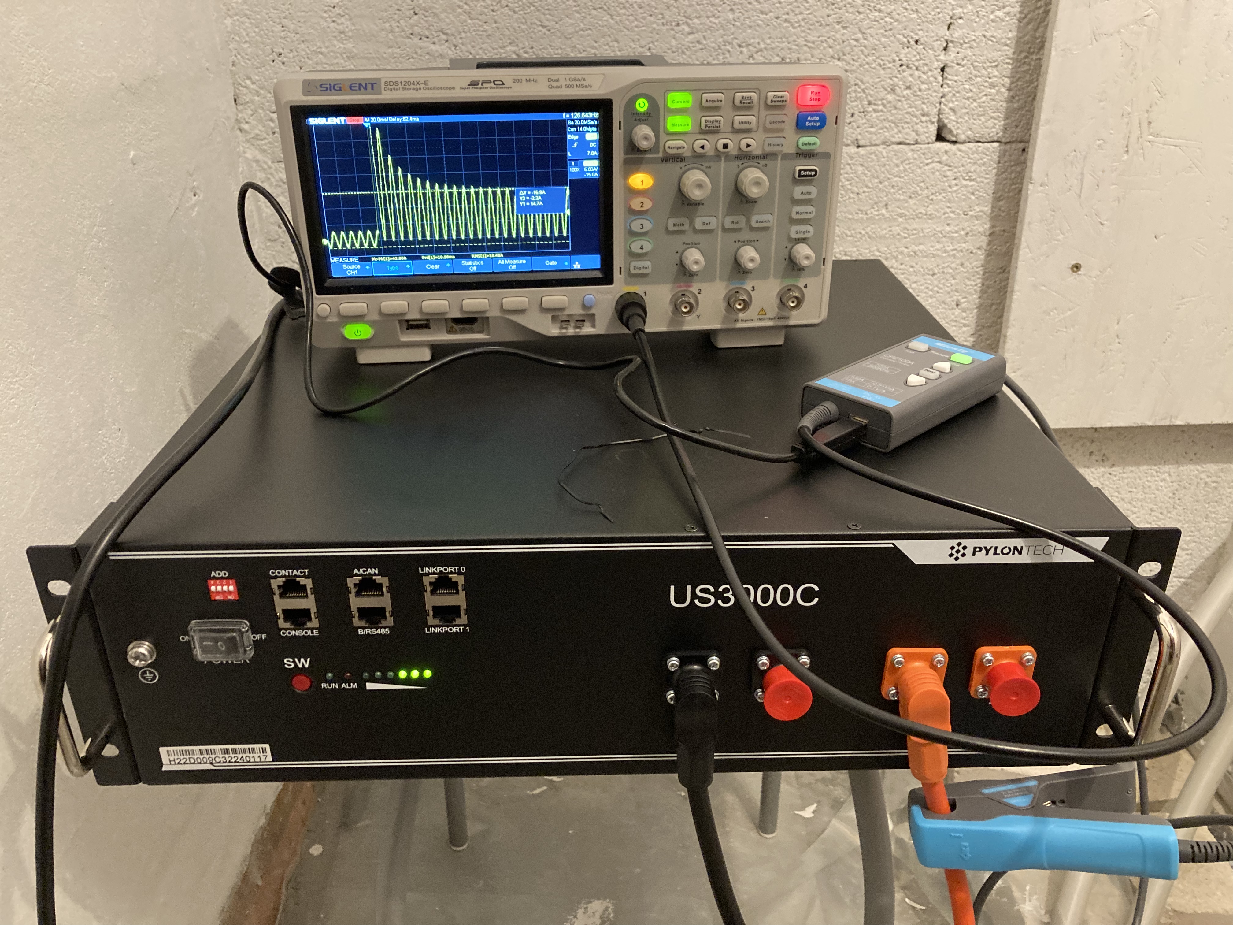
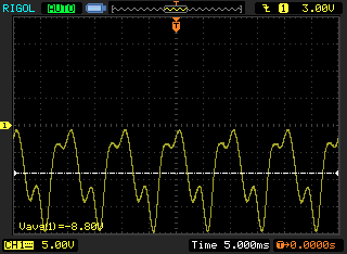
Average value of -8.8A ("-" due to battery discharging) corresponds quite well to the expected value. But I was a bit shocked by the shape which rises up to max. values of -20A. I was wondering whether this current shape is harmful for the battery. So I tried to get some information about the battery current ripple, that's why I found this post.

@echidna: I totally agree with you that the PWM switching frequent part of the current ripple comes from the DC capacitors inside the multiplus. (Remark: Analysing the DC charging current curve using a precharging resistor while connecting the battery shows a DC capacity of approx. 3mF). This capacity is by far not sufficient to supply the 2x grid frequent (2x50Hz = 100Hz in my case) part of the DC current - thus it must be delivered mainly by the battery. I also agree that a lower impedance of the battery connection / battery itself results in a lower DC voltage ripple but a higher battery current ripple.

This DC current component should be a sin^2(2pi50Hz*t) = 1-cos(100Hz*t).

In addition, there is the magnetizing current of the transformer (which has also be delivered by the batteries). This adds a sin(2pi100Hz*t); it has an average value of zero. This can be clearly seen when the inverter is in "no load" operation and does not feed / charge any power to / from the grid.

But in reality there are other harmonic components in battery current which result from massive 3rd and 5th grid current harmonics. I also did some quick analysis of the AC grid current, which show a 3rd harmonic of approx 30% and a 5th harmonic of approx 60% of the fundamental.
This is the grid current:
(again 1V = 1A):
load400w-grid.png
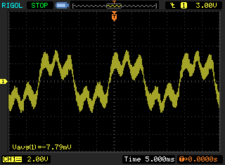
My questions for now:

  • @echidna: You mentioned that the statement "...ripple acts as a mini cycle of the battery" is wrong. Could you explain on that? Or provide some references? In fact, the 100Hz + harmonics of the battery current is higher than the DC-component in my case. I never got any experience with batteries, but I can hardly believe that such a ripple has no or only minor influence on battery life.
  • Why does the grid current include massive 3rd and 5th harmonics? I was expecting a nearly sine grid current. Maybe I did also some kind of misconfiguration of the multiplus(?)
  • Does anybody have measurements of grid / battery currents in order to verify my findings?

    I will take some more current and also voltage probes and a better oscilloscope within the next days and do additional measurements.

load400w-bat.png (4.5 KiB)
load400w-grid.png (4.5 KiB)
1 comment
2 |3000

Up to 8 attachments (including images) can be used with a maximum of 190.8 MiB each and 286.6 MiB total.

wkirby avatar image wkirby ♦♦ commented ·
Fun times. Thank you.

I'd expect very weird current waveforms to be produced when feeding in to the network. All kinds of unknown loads and other migrogenerators on your substation. Then consider the neutral current on that substation transformer with the other two phases, 300Hz peaks with goodness knows what harmonics.

Much better to conduct another experiment with your inverter in island mode driving a resistive load to measure current waveform.
Keep us posted.

0 Likes 0 ·
Trevor Bird avatar image
Trevor Bird answered ·

Hello @fabianm , interesting to see those waveforms. I have no experience with feeding the grid by the way but surely that current waveform is reasonable for a device providing a 50 hz sine wave from a DC source? Surely we wouldn’t expect to see a perfectly constant DC current? We can see the harmonic distortion of the waveform as it is not a sine wave and the odd order harmonics would make sense from a device that may be switching ( effectively providing a square wave) which comprises of those odd order harmonics in the frequency domain.

Most concerns as you know come from DC ripple voltage resulting from a relatively high impedance between the battery and the Multiplus. You of course are measuring DC current which is interesting but not a concern from a design perspective.

Great to see those waveforms. Gives me a better perspective and a clear idea on the type of load offered to the batteries so thanks,

Regards

Trevor

2 |3000

Up to 8 attachments (including images) can be used with a maximum of 190.8 MiB each and 286.6 MiB total.

echidna avatar image
echidna answered ·

Fabianm - just a quick answer now as I have to go out soon. The behavior of batteries (and electrochemical systems in general) for AC currents is a complicated topic. I'm a (retired) physicist, not a specialist electrochemist, but I have a basic understanding of the physics involved. AC impedance measurements are employed in electrochemistry to diagnose and characterize systems, with different effects dominating in different frequency ranges. The complex impedance (magnitude plus phase) is typically displayed on a so-called Cole-Cole plot, and if you google this term, you should find some useful explanations.

In the 100-120Hz area, you can expect a large part of AC current flowing through a battery to be supported by the double-layer capacitance (the same effect employed in ultra-capacitors) at the electrodes and not to be involved in ionic reactions. So the idea of "mini-charge cycles" is rather misconceived.

That is not to say that there are not deleterious effects from ripple currents, and from my brief reading (I no longer have ready access to the behind-paywall research literature), this is a topic of active research in the EV area, but I'm not sure how applicable any of this work is to our situation, as much higher DC currents are involved, but with polyphase AC systems and generally higher frequencies.

2 |3000

Up to 8 attachments (including images) can be used with a maximum of 190.8 MiB each and 286.6 MiB total.

echidna avatar image
echidna answered ·

Fabianm - one other comment - I have Quattro 48/10k's ready for commissioning, so have only limited actual data so far. But I have measured the capacitance at the DC terminals as about 100mF and confirmed this by examination of the capacitors at the bridge assembly. So I would expect around 30mF, not 3mF for your case - unless the Multiplus II design is significantly different.

It would be interesting to know what is in the Multiplus II. The Quattro uses a whole bunch of 3.9mF and 1.2mF electrolytic. Possibly the MPII is using smaller value but lower ESR non-electrolytic capacitors.

2 |3000

Up to 8 attachments (including images) can be used with a maximum of 190.8 MiB each and 286.6 MiB total.

fabianm avatar image
fabianm answered ·

Dear Echidna,

thank you for your answers. I will search IEEE xplore for publications on this topic. I also thought about EV applications, but I'm 99% sure you will not have 100Hz ripple in this kind of application as with 3-phase systems the battery power should be more or less constant (for a stationary working point). It should not contain ripple of 2x motor frequency etc. Changes of load point (acceleration / braking) should also only occur with much lower frequencies (maybe 1.. max.5 Hz). This 100Hz ripple is definitely a situation which only applies to nature of one phase systems.

I measured charging current (green) / voltage (purple) of the MP2 3kVA at the battery connection terminals again. The charging resistor used by me is of 270 Ohms. Initial current is 50V/270Ohm ~ 180mA and the time constant is around 1...1.5s = R*C as you can see in the plot. So this leads to C = 3...5mF.charge-dc.png
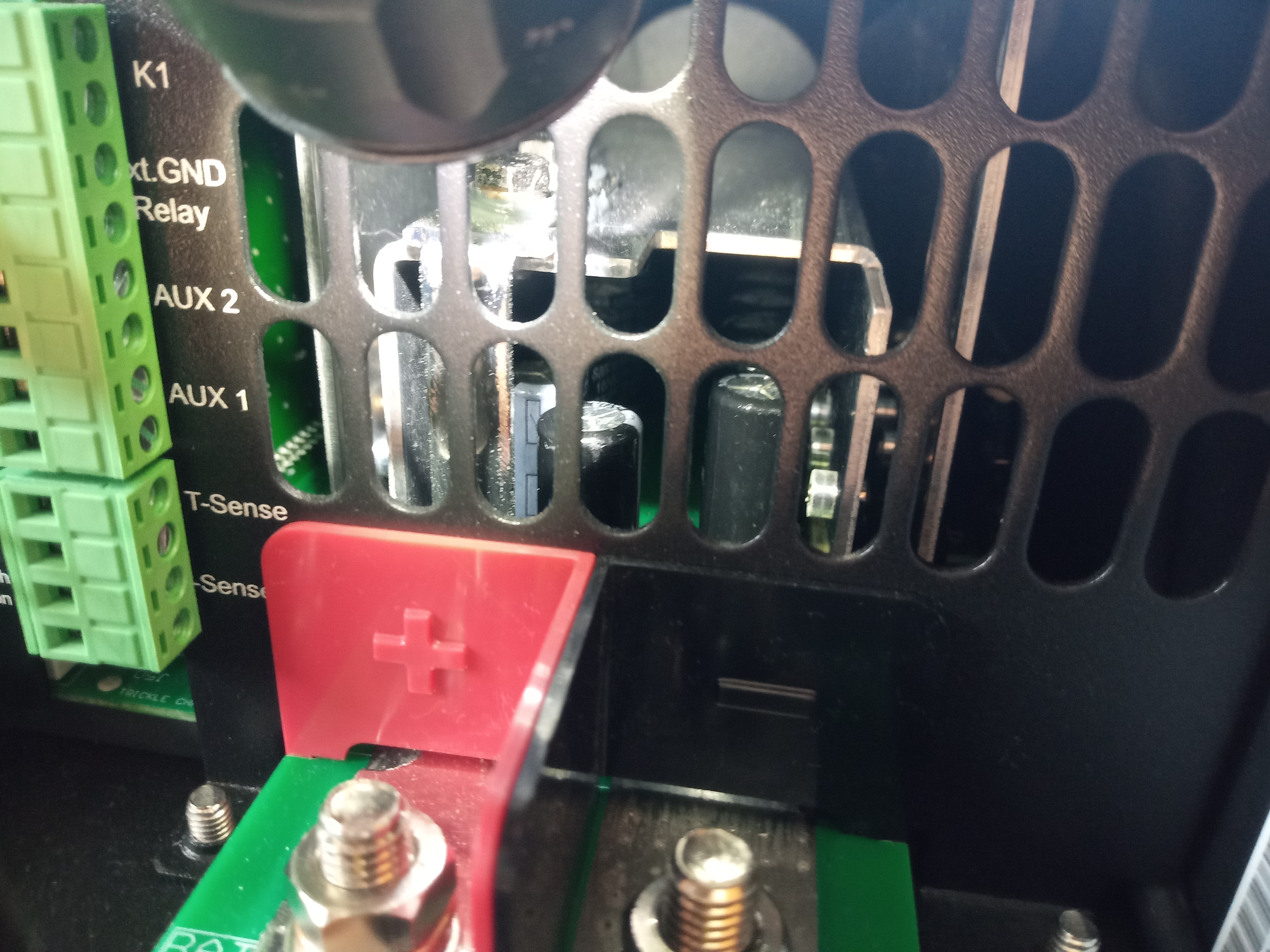
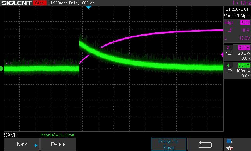
It might be possible (but unlikely from my point of view) that Victron uses internal precharging relay which connects additional capacitance when DC is fully charged. I do not want to open my MP. But through the cooling slots near the battery terminals I can see a 12 or 13 pieces capacitor bench of 330uF each capacitor. This fits to the measurment. Those capacitors are located under the Mosfet cooling plates.

Also, in this video, no other capacitors at the 48V DC are visible:

https://www.youtube.com/watch?v=_vRhzrNa3oM

Fabian


charge-dc.png (26.8 KiB)
2 |3000

Up to 8 attachments (including images) can be used with a maximum of 190.8 MiB each and 286.6 MiB total.

fabianm avatar image
fabianm answered ·

Here you can see some of the capacitors:

dc-capacitors.jpg

They are Sancon RE Series 330uF / 100V.

It seems to me that the inner (inverted U-shaped) aluminum sheet is DC+ and the outer sheets left and right are out1 / out2 connected to the transformer.


dc-capacitors.jpg (4.3 MiB)
2 |3000

Up to 8 attachments (including images) can be used with a maximum of 190.8 MiB each and 286.6 MiB total.

janieronen avatar image
janieronen answered ·

What an interesting topic and appreciate your professional take on this. Few points about the test setup: Please keep in mind that I am not professional with that topic but have seen similar results in my testing.

1. Original Quattro and Multiplus are working with lower frequency PWM(20khz) for switching MOSFETs and due to design have larger capacitor banks and transformers with high inductance. New model 2 versions due to high-frequency topology have different characteristics and even VE announced the same ripple limits they act differently when you test these with out-of-specs capacity batteries.


2. Yes total ripple current will increase when adding a larger battery bank as battery bank total internal resistance is lower. however, that is not a that bad thing as with a larger battery bank one cell /string will take a smaller part of this ripple stress when shared with parallel cells and strings. With lower resistance bank provides more energy(current) when needed and ripple voltage will stay within limits.

And if we go back to the original point about the longevity of capacitors and batteries. I have not seen other brands in the field dimensioning their components with the same headroom as VE with the original multi/Quattro. I have replaced a lot of other brands' equipment on the field with Victron products as these have proven to outlive many competitor products. Also, batteries have exceeded promised cycle rates when bank dimensioned with proposed capacity. I am not an official reseller or linked to VE. I am just an electrician with my own company and choose products I have seen to perform as promised in their price class.

2 |3000

Up to 8 attachments (including images) can be used with a maximum of 190.8 MiB each and 286.6 MiB total.

echidna avatar image
echidna answered ·

Fabianm: Interesting about apparently confirming the much lower value of the the MP II capacitors.

The primary requirement for these capacitors is I believe to support the switching frequency (20kHz or so) current. A large capacitance (such as the Quattro has) is not necessary per se for this, but considerations of allowable capacitor current (and hence heating and reduction in life span) and capacitor ESR may have lead to a larger capacitance being used. Sam Ben-Yaakov (retired [?] Israeli EE prof. specializing in converter design) has some excellent YouTube videos, including one on the choice of DC side capacitors (although in the context of 3-phase converters, so focussed on the switching frequency currents): https://www.youtube.com/watch?v=ovzeCSx7yH4.

I was in a hurry in my previous answer about Victron's statement that "...ripple acts as a mini cycle of the battery". To add some more: what is implicit in this statement I think is the idea that both charge and discharge are happening in the presence of ripple current in battery connection.

In fact, with a resistive AC load (AC voltage and current in phase), the current at the DC bridge terminals will be unidirectional (discharge only), varying from zero to twice the average DC value.

However, with AC load power factor deviating from unity, you can in fact have reversal of the "DC" current. Obviously (to take an extreme, theoretical case which might be outside the operating envelope of the converter), with a pure inductive or capacitive AC load, there is no net AC power output, so for an ideal PWM converter (no losses), the average DC current must be zero, but with large 100Hz oscillations around zero. With more normal power factors, the reversal current should be fairly small. What this does to the battery is an open question.

2 |3000

Up to 8 attachments (including images) can be used with a maximum of 190.8 MiB each and 286.6 MiB total.

echidna avatar image
echidna answered ·

In my spare time, I've been poking around for research information about effect of ripple current on battery performance. The following is perhaps the most useful reference I have yet found in open literature:

https://www.sciencedirect.com/science/article/pii/S030626191630808X

Now granted, it is for quite a different cell type, namely 3Ah 18650 NCA Li-ion cells. But a lot of the discussion is more generally applicable. The results, as with most other information I've come across, suggest that the effect of large current ripple (at around 2x power line frequencies) on Li-Ion aging is noticeable, but probably not too serious.

One effect covered is increased cell heating with ripple, and since elevated cell temperatures are linked to more rapid aging, this is of some concern. If the "DC" battery current (as with the regular Victron inverter design) has (for AC load power factor = 1) a sinusoidal waveform at 2x line frequency, and varying from zero to twice the average DC current, then we know the heating effect of that battery current waveform is 50% greater than the value calculated from the average DC current. This effects heating in wiring, switches, fuses, etc. in the path between the battery bank and the inverter, and also within the batteries, although losses in the latter are more complicated than for simple ohmic resistors.

As janieronen's comment suggests, probably the best we can do is share that current over as many parallel strings as practical (employ a large bank).


2 |3000

Up to 8 attachments (including images) can be used with a maximum of 190.8 MiB each and 286.6 MiB total.

power4me avatar image
power4me answered ·

Very interesting thread and a lot of accumulated knowledge!

I was wondering if the number of batteries to share that current is the only measure.

I am building an 3-phase ESS with Multiplus II 5000 48 and Pylontech US3000C Batteries. In a typical household application the 3 phases are most of the time not symmetrically loaded, so in some cases ripple like in a one phase system are present.

For a quick test I hooked up one Battery to one Victron measuring the battery current with a current probe. Without load, the current flows back and forth around Zero. Applying a 300W halogen lamp as a test load, the current flows from the battery to the inverter. (When I did the test, I had no intention to post, otherwise I would have taken a proper screen-shot, sorry).

00f38ff1-635f-4274-976b-a4af1acd6995.jpeg

The battery cable is 2x 2 meters and acting as an inductor before the batteries „capacitance“. Wouldn’t it help to place a capacitor (-bank) close to the inverter to supply the ripple current to the inverter out of the capacitor instead from the batteries? I found a 15mF 100V 85°C 20000h for around 40€. If one or several capacitors would help to reduce the losses unload the ripple from the batteries and prolong the life of the expensive batteries it could be a good investment.

Please share your thoughts about adding a capacitor bank close to the inverters!


2 |3000

Up to 8 attachments (including images) can be used with a maximum of 190.8 MiB each and 286.6 MiB total.

echidna avatar image
echidna answered ·

The first thing you need to know is the battery impedance at the ripple frequency. I don't know how many batteries you will be paralleling or what their characteristics are, but to take my case, with 4s,4p Victron 12.8V 330Ah (16 batteries, 48V, 1320Ah for the bank), the impedance of the bank (not counting any wiring) is of order 1mOhm at 100Hz.

To equal that with a capacitor you need about 1.6F (that's Farads!); an inductance of 1.6uH will have the same impedance at 100Hz, or about 6m of 4/0 cable will have the same resistance.

Of course, in practice wiring (including fuses, switches, shunts, etc.) adds resistance and inductance. In my case the wiring (etc.) will add about 200-300 uOhm effective for the bank.

Inductance is minimized by cable routing, but is hard to estimate accurately. Running positive and negative cables in close contact should reduce inductance to of order 0.5uH per meter. of course, that is not always possible. Running separate pairs of cables from each paralleled battery (string) to a junction near the inverters will also help reduce inductance. In my case, with 4 parallel strings and reasonable care in routing, I expect maybe 0.5uH (no more than 1uH) effective inductance for the bank at the inverter terminals.

Your best "defense" is a large bank with optimized (short, fat, close-together) interconnects.

Adding a large capacitance at the inverter terminals (by large I mean a good fraction of 1F here) and failing to minimize the cable inductance could actually be counter-productive, as you risk creating a a (heavily-damped) parallel-resonant circuit which could actually increase ripple at the inverter terminals.


To check how effective your system is, you should measure ripple voltage across the battery terminals, and across the inverter terminals (ideally with a differential oscilloscope probe, or alternatively with a floating digital meter, and keeping short test leads, twisted together to minimize inductive pickup).


And before you talk about prolonging battery life, I would like to see some proper, research-based evidence that their life is significantly reduced by ripple in practical applications. I'm not saying there is not some degradation of life - just that I've yet to see anything much better than urban legends or hand-waving to justify such claims. These tend to take on a "life" of their own through repetition (but usually without attribution).

Bear in mind this is not an easy thing to measure realistically. It needs to be done on representative cell designs, over thousands of charge-discharge cycles, with the sort of currents and ripple we have with these inverters (not what occurs say in EV motor drive systems), and at ordinary temperatures (not accelerated aging at extreme high cell temperatures) - and then compared with operation at similar DC currents without ripple.

If reduction of battery life by ripple is a serious concern, there is a much better solution, and that is inverter designs which do not create large ripple currents on the DC side. Such designs do exist commercially (mentioning no competitor names here ;-)

2 |3000

Up to 8 attachments (including images) can be used with a maximum of 190.8 MiB each and 286.6 MiB total.

echidna avatar image
echidna answered ·

One more comment: in choosing capacitors to parallel across the inverter (and I am not recommending this), you need to be cognizant of the ripple rating of these capacitors. Heating of the capacitors by ripple current flowing through them can be a limiting factor (it may limit capacitor life to well below the rated 20000h or whatever). This is presumably a major reason why Victron limit the ripple voltage at the inverter terminals, to avoid excessive heating of the input capacitors inside the inverter. Other inverter manufacturers (e.g., Outback) actually monitor and report the inverter input capacitor temperature, and set a maximum temperature criterion.

2 |3000

Up to 8 attachments (including images) can be used with a maximum of 190.8 MiB each and 286.6 MiB total.

power4me avatar image
power4me answered ·

@echidna:

Thank you for the detailed answer!

Reducing inductance by routing the DC cables in close contact is definitely a good thing to do and what I intend to do. As in PCB design you want to have the the area between power traces as minimal as possible to reduce inductance and minimize EMC issues. I was wondering why this is not mentioned in the manuals or recommendations. (Or did I miss it)

2 |3000

Up to 8 attachments (including images) can be used with a maximum of 190.8 MiB each and 286.6 MiB total.