I have a 2 phase system on property which means I have 2 live wires and one neutral.
For an off grid system set up I was going to have 2 separate systems, an inverter connected to each line and share the neutral with
x2 inverters (Quattro's 10kva 48v)
x2 battery banks
x2 sets of mppts
and separate arrays of solar panels for each system
However I have since learned that there could be a better set up by combining the inverters together in parallel. Single battery bank, one set of mppt's and solar panels for single system.
This would mean I may have to connect the two positive lines together and power both phases as one with the two inverters paralleled as master/slave.
This would allow all the power of both inverters to go to both positive lines and power can be used by either line at different times or at the same time. Maybe this could work, not sure?
Or is it possible to set them up as you would do to parallel the two inverters together as master and slave using the same battery and mppt's and have the neutral common to both inverters but have separate positives where each inverter is connected to a different positive line.. They would be loaded very differently at different times would this be ok? I don't know.
asked
Best setup for 2 quatros with 2 positive lines, one neutral line off grid
It's going to be difficult to provide good answer without first knowing for sure what those two line conductors are. Are they the same phase (0°) , are they two phase (120° / 240°) or split phase (180°)? If your two line conductors are different phases then you cannot configure the two Quattro's in parallel. You would need to configure them as two phase or split phase depending upon how the phases of the two incoming lines. An answer about the neutral conductors would follow on from here.
Better to have this information in hand before providing an answer otherwise will will go round and round in circles.
In any case, it's always better to have one system battery bank and all MPPT's feeding the one battery bank as one simple system.
Thank you wkirby, However Its not grid connected system . Its just the wiring in place that is to be used for an off grid system with 2 inverters as mentioned above. Can I please have help with the above questions, I did say it was off grid system even in the heading.
Sorry, I missed the off-grid part.
So if you have two line conductors to feed circuits downstream and you don't care about the phase relationship between the two then the best thing would be a parallel system.
Configure the two Quattros as a parallel system and wire them to one common distribution board, Take both line and neutral from each, don't share a neutral because the line and neutral current will be the same from each Quattro. The two Quattros will share the load equally.
Then from the distribution board the two line conductors that you have can be taken off from different circuits. Your electrician would offer you the best advice here in order to conform to your local wiring regulations.
So I get the paralleling of the inverters but are you saying to connect both positive outputs from the inverters together then the two lines would also be connected together they will be acting as two distribution lines from single two inverter source. I don't understand how the neutral from the inverters are not connected together. I have only one neutral wire for the whole property, how can it not be shared or connected to both inverters? What do I do with neutral? I just dont understand what you are saying here.
Or are you saying to separate the outputs from both inverters therfore positive from each inverter goes to separate lines they will have different loads, but still the neutral will have to be common to both though.
Basically what I need to understand is that when using the 2 inverters in parallel can I have different loading on separate inverters having the positive outputs going to different lines and different loads.
or
Connect both inverter positive outputs together thereby all loads on both lines will be connected to both inverters therefore all loads will draw from both inverters.
and what happens to the neutral
Which ever way the set up is I still only have one neutral line and surly it would have to be connected to both inverters which ever way chosen is best.
Take the line and the neutral from each Quattro and then combine them in a main distribution board. Now the two Quattros are providing a single source of power at that distribution board.
From there you can take power to you existing two line conductors off of two separate circuit breakers.
So now another twist, what is the CSA of your neutral conductor? Is it the same as one of the line conductors? If it is the same then parallel inverters would not be suitable because the neutral current would perhaps be too high, you would have to go with split phase or two phase to keep the average neutral current down. This depends upon you local wiring regulations - ask your electrician about that.
Even in split phase or two phase take line and neutral from each Quattro to combine the neutrals at a distribution board and then separate phases to each of your line conductors going out.
Sorry about the confusion, it is an unusual arrangement I am not there to see it. I have to build a picture in my head. I can tell you how to get from the Quattros to a main distribution board to combine those conductors - always both line and neutral from the Quattros to the board. From that point your electrician needs to offer you the proper advice.
Yes it is an unusual situation.
In the first paragraph for paralleled inverters when you say combine them in the distribution board are you meaning connect the two positives from each inverter together in the distribution board? So the positives from both inverters are connected together and the negatives from each inverter are connected together in the distribution board. I still don't know if you are saying to connect the positives of the inverters together or have them separated to individual loads.
The CSA of the neutral conductor is the same as the line conductors and they are quite a distance from the distribution board around 70meters and they are very large, I don't know the cross section area but the core is around 8 or 9mm in diameter because of the distance. Two phase may be a good way to go but I have never seen any instructions on how to do this, there is 3 phase, split phase but I have never seen two phase system set up instructions.
Where you say always both line and neutral from the Quattros to the board, this will be impossible for me as the board is at the other end of a 70 meter wire (3 separate wires 2 positives and 1 neutral), The two positive lines are ok but the neutral has to be connected together where the inverters are. Is this still ok to do, I don't see why not. Even the positives for a paralleled system if you are meaning to connect them together in the board it would be far better to do this at the inverter side.
I hope this give you a better idea of my set up.
You need a board close to the Quattros to combine the conductors coming out of them before connecting your existing 70m lines.
We are not looking at connecting those 70m lines directly to the Quattro terminals, they need to go into a board local to the Quattros.
Combine the neutrals here onto a common busbar and then for two phase each line L1 and L2 can go to a circuit breaker and then connect your 70m line conductors here and the single neutral conductor goes to the neutral busbar.
Two phase is definitely a configuration option for Quattros: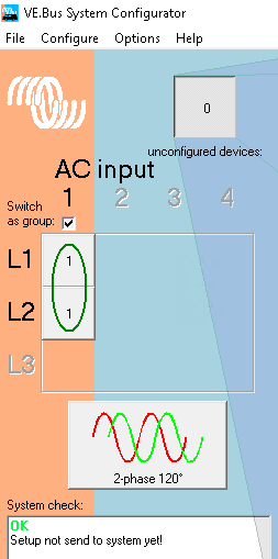
Ignore AC Input because you don't have one in off-grid.
Also to clarify, we are talking about the AC conductors here. You keep making references to positive, but I'm assuming that you mean line?
In AC there is no positive or negative conductors, only line, neutral and earth. The DC side of the Quattro will have positive and negative cables.
I don't want to sound pedantic, but want to be sure that we are on the same thinking.
Thanks good to know that 2 phase is an option, would you set up everything much the same as three phase but choose what you have shown in picture? It looks quite easy to do. I presume the configure program may intuitively know there are only 2 inverters connected.
With ac conductors when I say positive I am referring to line sorry about that. Just trying to emphasis live wire from inverter.
Now with a parallel set up just for me to have the understanding can you just confirm about the output lines of the 2 inverters are connected together in a close local board then to separate circuit breakers then to respective 70 meter cables. And the neutral lines are connected together in the local board on bus bar with 70 meter neutral line. So the output from the inverters are not separate but act as a single source. And that the inverters if connected in parallel shouldn't have separate loads connected to individual inverters.
Another thing I would like to know is that there is a dormant 5kw solar system already connected to one line. Once there is power in the line it will power up, would this have any bearing to the overall set up. I was hoping it could not only be used to have greater power available on that particular line but also to help charge the battery bank through one of the inverters.
OK with tow Quattros configured in parallel (single phase), it will be almost the same as the two pahse. Take line and neutral from each Quattro to the local distribution board, each line into its own circuit breaker, but the difference is that you will have a busbar for line conductors to come out of the circuit breakers and common the two lines from the Quattros after the circuit breakers. Then those two 70m line conductors can also connect to this busbar.
But like I said before, for parallel operation, we need to be sure that we do not overload the neutral conductor. The neutral will need to carry the current from both of your line conductors at the same time. With two 10kVA Quattros, that neutral conductor could see 90A. Make sure that neutral conductor is capable of this.
5kW solar array on one line is OK, your Quattro is 10kVA so easily below the factor 1.0 rule. It will power up the PV inverter and it will operate. But, you need to configure that Quattro (or both if configured for parallel) for this PV. It needs to know it is there so that is can accept the surplus PV to charge the battery and also to increase the frequency to slow or shut the PV down if the battery is full.
More details here:
https://www.victronenergy.com/live/ac_coupling:start
Thanks for the help I am getting a good idea of possible set ups.
Two phase may very well be the best path.
Is what has worried me is that even in that link it references "single-phase, split-phase and also three-phase systems" As everywhere possible set ups are discussed by victron this is all I see mentioned, however 2 phase is never mentioned, I have never seen it being stated.
A split system is not the same as 2 phase.
I never believed 2 phase system could be set up because it is never mentioned, this would also mean setting a phase relationship. But you are showing that it can. I hope you are correct.
Maybe you could elaborate why 2 phase is missing from victrons literature.
2 phase is very unusual, that is why not much is said about it.
Common systems are single phase and three phase. Split phase is very popular in America.
The screenshot that I showed you earlier is from the actual configuration software, so it is very possible to configure 2 phase. In fact there are two options for 2 phase configuration, 120°and 240°.
I am so glad you have showed it, I think victron should make a point to at least show in some regard this option. So people know it can be done.
Another thing I was looking at as a possibility but unsure as I am looking at as many initial possibilities at this time.
This is a kind of hybrid set up using only one inverter.
In my case Is it at all possible to have one line L1 coming in off the grid being grid connected while L2 being completely disconnected from grid. And at the other side of 70 meter cables use L2 for solar. Having both grid on one line and solar on the other. The only problem would be the neutral as it would be shared and at opposite sides of 70 meter cables would this present a problem.
Also for the two phase set up I am presuming that I just follow the 3 phase system set up but make the changes as shown in the picture you have shown. All else should be the same.
Also I see my previous thread has been brought up where you and others helped me out with my situation but that was when I was trying to go for a grid tied system however this became to problematic, I have decided to connect the quattros off grid as it becomes alot easier, and because of the distance of the inverters to the main meter virtually impossible to do. So I started again I probably should have looked it over to refresh my memory as we have been over similar things in the end however I started aiming at paralleled system but brought back around to 2 phase which is where we are now. Also as previously mentioned victron leaving out anything about 2 phase but still being possible has been a problem for me. But thankfully it can be done.
Really, "two phase" and "split phase" are the same thing. Both have two hot legs with some phase difference between them. Split phase usually implies the phase difference is 180 degrees but the same wiring is also used (at least in the US) when two legs of 3-phase power feed the panel. In this case the phase angle is 120 degrees. This happens when the incoming grid is three phase but the distribution panel only has 2 legs. An example of this would be an RV park supplying "120/240" volt 50 amp service when the park receives 3-phase power from the power company.
180 degree two-leg power minimizes the neutral current since the two hot legs pull against each other. A perfectly balanced load will result in no neutral current. In a system with 120 degrees between legs, there is always some neutral current even with equal loads on both legs.
I would recommend setting a two-leg off grid system up for a phase angle of 180 degrees.
I thought split systems have half the voltage.
Would the two leg system with phase angle of 180 degrees be a split system which as far as I am aware has half the voltage on each of the 2 lines, or 2 phase with 180 degree angle with 240v on each line. This is where I see a difference. I need 240v on each line.
For US power, each leg is 120 volts relative to neutral. A 180 degree two-phase ( a true split-phase system) has 240 volts leg to leg. A two-phase system with a 120 degree phase angle (two legs of 3 phase) has 208 volts between the two hot legs. It the US, three phase power is usually seen only in commercial buildings. Most residential services are split phase, 180 degrees.
Voltage on each leg for different power systems will be scaled in a similar manner. So for a split-phase 230 volt system, you'd see 460 volts between the two legs for a 180 degree angle. For two legs of 3-phase, the leg to leg voltage would be about 400 volts. I'm not sure how often you'd come across one or the other.
So what you probably want to do is purchase Quatros with a 230 volt AC path and connect them in a two-phase 180 degree system.
Yes it is an unusual situation.
In the first paragraph for paralleled inverters when you say combine them in the distribution board are you meaning connect the two positives from each inverter together in the distribution board? So the positives from both inverters are connected together and the negatives from each inverter are connected together in the distribution board. I still don't know if you are saying to connect the positives of the inverters together or have them separated to individual loads.
The CSA of the neutral conductor is the same as the line conductors and they are quite a distance from the distribution board around 70meters and they are very large, I don't know the cross section area but the core is around 8 or 9mm in diameter because of the distance. Two phase may be a good way to go but I have never seen any instructions on how to do this, there is 3 phase, split phase but I have never seen two phase system set up instructions.
Where you say always both line and neutral from the Quattros to the board, this will be impossible for me as the board is at the other end of a 70 meter wire (3 separate wires 2 positives and 1 neutral), The two positive lines are ok but the neutral has to be connected together where the inverters are. Is this still ok to do, I don't see why not. Even the positives for a paralleled system if you are meaning to connect them together in the board it would be far better to do this at the inverter side.
I hope this give you a better idea of my set up.
Please, please, please consult a professional for the design of this system. There's obviously an understanding you lack and proceeding on your own could be hazardous.
If you parallel the inverters, the outputs MUST be connected together with equal-length cables. (hot to hot, neutral to neutral).
If you parallel the inverters and connect them together near the inverters, the neutral current will be double that of the hot leg conductors. So you'd need double the area for the neutral. That's apparently something you can not do, so you may delimited to a 2-phase system.
One more time: "2-phase" is the same as "split phase". Use any of the multiphase diagrams and just remove the third leg.
I do not know why but I posted this 8 days ago and for some reason it has re-emerged, I never posted it 2 days ago when it has shown on this thread again. I don't know why it came up I didn't do it. This question was answered by wkirby 8 days ago, and I have since moved quite far ahead in the system design.
I am definitely going for 2 phase set up at 180 degrees, as you have advised a while ago. And as I have previously mentioned the distance is now 220 meters and area of the cables are 23.31mm squared each (x3).
I really appreciate all of your help anyway even though the question has doubled up for some reason.
Just with your last thing where you say just remove the third leg. Not sure what you are referring to however will be just using L1 out on each inverter giving the two phases and sharing the neutral on each inverter. And leave out L2 out on each inverter.
L1 out on master inverter will be L1
L1 out on slave inverter will be L2
Neutrals out from each inverter are connected togeter as shared neutral line.
Hello
@WKirby
Sorry to resurrect an old thread but you seem knowledgeable about parallel connections. My setup is almost identical: off-grid, 2 Quattros 10KVA, 1 battery bank, 1 Cerbo, 2 MPPTs 250/100 but my property is wired for single phase 240V AC. 1 Quattro is still sitting idle. The second one is connected and working fine.
I thought I had all my bases covered until I read in your informative comments that one has to be careful that the neutral CSA (I guess that means Cross Section Area) is not too high. That threw me off as this particular subject doesn't appear to be covered by Victron docs and training videos.
My plan was to take the live and neutral from the two inverters to an AC combiner. The 2 live wires would pass though 2 AC breakers. The AC combiner would combine the electricity from the 2 inverters and output 1 live and 1 neutral to be distributed to various AC loads. I'm yet to figure out what to do with the 2 inverters ground outputs, since they can't go into the combiner. I also have to figure out where to get the ground wire to distribute to the loads since it can't come from the combiner (there are no combiners which provide a ground output on the local market). So I have 2 questions:
1. How do I mitigate the neutral's CSA? Can I use just 1 neutral from 1 inverter? Noted that my current setup with 1 neutral from 1 inverter works.
2. Where do I get ground from? Currently, I get it from my 1 connected inverter.
Where I live, getting a professional is not an option. You have to tell them what to do and they have no interest in learning. They simply fry your equipment and disappear.
Thanks.
Whether you connect the Quatros in true parallel operation or two/split phase depends on your distribution system and the loads connected to it.
Are there any loads that connect to both hot legs through a dual breaker? If so, I would guess that these loads need double the voltage of loads that connect to one hot and the neutral. If this is the case, then you want to configure the Quatros as a two-phase system, then set the phase relationship, to match what your loads expect, probably 180 degrees. This makes a "split phase" system.
Paralleling Quatros (not multiphase) requires all cables in and out AC and DC to be of matched length. That is the positive battery cables must be equal length to some common point. Same for the battery negative, same for the AC hot and AC neutral connections. Any cable length differences will result in the Quatros not sharing the load equally. If you go this route, you would need a common point for your AC hot legs, then run separate hots from that point to each leg of your distribution panel.
There is a good tutorial on multiple inverter/charger design and setup on Victron Professional. This will answer most of your questions. The account is free.
Hi Kevin,
There aren't any shared loads on the two phases that I can see. However the loads seem quite shared throughout property through the 2 individual phases.
Paralleling the Quatros is something I was thinking of doing, I was also considering running two separate systems with shared neutral but after help from wkirby I am now looking at 2 phase set up. It seems to be the simplest set up. I have been trying to look at various options to choose something that will work best as I seem to have a bit of an unusual set up that I have to deal with. And its really quite confusing that victron has left the 2 phase set up out of its set ups, I cannot think why they would do this even if it is not that popular, just doesn't make sense. Thanks to wkirby he has shown that it looks quite easy to set up. Initially I was going to have it grid connected but brought with it its own problems, also as far as I am aware victron has lost its certification for the quatros in Victoria at the present time. Thanks for your advice.
There are two levels of "certification": the first is the ability to connect inverter/chargers to the grid; the second allows feeding back power to the grid (an Energy Storage System).
Since you appear to be struggling with this, I recommend you consult an electrical contractor familiar with off-grid or ESS systems or at least grid-connected inverter/chargers. There are simply too many opportunities for a DYI design to miss important issues and the consequences could be dangerous.
Hi Kevin
Thank you for all your help. I am thinking that your suggestion is by far the best set up option for me that I can see at this time with 2 phase set up of 2 Quattros with 180 degree phase shift.
I am finding that the loads on each phase are reasonable distributed throughout on my property, thus enabling a reasonable cancellation of load on the neutral conductor which is very important. The final positioning of solar system at this time is 220 meters from house loads and cross section area of a single conductor is 23.31 mm squared, and there are 3 separate conductors. So its important to keep the neutral as unloaded as possible.
May I ask that when 2 Quattros are set in 2 phase system with 180 degree phase shift. I am assuming that the transformers of the two quattros will be acting in a sense like a single transformer with a center tap, that center tap is the neutrals and the other end of each transformers from each quattro are the line 1 and line 2. Would this be correct?
The transformers and the two Quatros will be completely independent. While in concept it looks like one center tapped transformer, there is no magnetic coupling between the two like there would be in a single transformer with a center tapped secondary.
lets get some clarity
1. the site is 220volt 50hz
2. there is a generator involved somewhere
3. really you are calling this two separate systems for no electrical reason except that they go off to different areas.
If this is the case
1. then make ONE battery bank
2. set the two Quattros up as a Paralleled system this will then give you 20VA in TOTAL available to both circuits. ( this way you share the load and any one circuit can use the FULL systems output)
3. the Quattro outputs are then combined into one main feed in and you connect this to the ONE main incoming breaker in your switch board - then from there you run the different circuits off to as many locations as you like through separate breakers in preference.
4. up to you but a RCD breaker or equivalent breaker should be installed at least at the remoter switch boards.
I maybe wrong with the above but from everyone's reply's and your reply's I think this is what you are after - SO just KEEP IT SIMPLE.
Again you should get electrical advise from a qualified electrician. killing yourself or someone else down the track is not a good option.
If the above is wrong then a diagram of what you are proposing would be helpfull
Thanks Paul,
This is off grid.
No generator.
1 battery bank
2 Quattros
What you are saying may be the way to go but was concerned about neutral having to carry the power of both lines at the same time, Phase shifting can help with this.
The main loads are at the end of 70meter (x3 cables, L1,L2,neutral) cable from where the solar set up is but the cable is very large because of the distance, I haven't measured the area however around 8 or 9mm core diameter so maybe its good enough anyway.
A diagram would be most desirable. I'm also very interested in understanding the process of wiring it correctly.
@Kwame Have you looked at this?
It's a 3 phase system but relevant to parallel setup. The physical connections are the same.
Fideri