We are doing a Victron lithium conversion on our sailboat. The boat is currently wired for two 30 amp services (legs). There is a magnum inverter charger that has one leg passing through to panel. (Outlets) The other leg, (air/heat and water heater) going to panel. We want to upgrade to a multiplus II, and we are planning to install four blue smart 330 batteries. We will have plenty of battery juice and solar to have the ability to invert all loads if we want to, and want it wired so. I’m having trouble finding the best way to do this without converting the boat to a single 50 amp service. Lots of mixed feelings and threads gone dry around this very topic on forum. I’d like to nail down the best and most correct way to do this! Thanks!
asked
Sailboat with two 30 amp services, one multiplus II, wiring?
You can not safely connect two legs of shore power together. They may be on different phases and/or have different neutrals. If they are fed with an RCD/GFCI then connecting the two neutrals together in your boat will probably trip the RCD/GFCI.
Another issue with boats is the shore power may be of different voltage and current. Shore power may also be single phase or split phase.
One possible solution would be to not feed shore power to the Multi and use it only for inverting. Shore power would connect to one or more dual-voltage chargers. This way, the loads in your boat always see the same voltage and frequency and you can accommodate multiple shore power scenarios.
Another possibility is to incorporate an isolation transformer with multiple "taps" on it's input in order to accommodate different shore power voltages. The Victron 3600 watt isolation transformer will automatically switch between 115 and 230 volts.
Thanks for the info Kevin. You seem to be pretty knowledgeable on the whole shore situation. I definitely want to try to use just one unit. And doesn’t the multiplus II have a transformer in it already?
I have tabbed up our AC loads
AC/Heat - 10 amps
Microwave - 10 amps
Space Heater(low) - 5 amps
Water Heater - 7 amps
Multiplus II - 15 amps
IP 22 12/30 charger - 6 amps
max total of everything running at once - 48 amps
—————————————
I realize that’s almost 50 amps if everything was on at once, which it wouldn’t be. Which is why converting to a 50 amp service at first, made the most sense. I know the mulitplus II is capable of 50 amps input AC.
So there is no way to keep your separate legs from pedestal but wire it at the multi similar to a 50 amp service, adding hot from L2 to the corresponding pin on AC Input 1 on the multi II and then just combining the neutrals? Essentially wiring it up as a 50 amp service?
Thanks
The Multi does have a transformer but it is not in the AC path. One side of the transformer connects across the AC output and the other connects to the DC circuitry of the inverter.
Most of the Multi and Quatros handle a single leg both in and out. Multis (except for the Compact) have two AC outputs, one for critical loads, the other for loads that shut down when there is no AC input. Quatros also have two AC inputs, one for grid/shore and one for generator. Only one input is in use at any given time.
You didn't specify shore power voltage, but the Multiplus II 2x 120V supports 120/240 split phase power OR 120 volt single phase power. It has two hot legs in and two hot legs out. The inverter sits across leg 1 with leg 2 going through the unit. Leg 1 would get power assist, leg 2 not. There is logic to detect split phase power or power only on leg 1 (120 volt shore power). When a single leg input is detected, or when no shore power is present and the Multi is inverting, it connects leg 2 output to the leg 1 path so both legs are powered, but 0 volts between them. (Generally in an RV, there are no 240 volt loads so this works out OK.) The unit is 3000 VA so you'd be able to extract 25 amps from the unit (total for both legs) while inverting.
This Multi would not support our two existing 30 amp shore power connections since the neutrals would need to be connected together. I also believe the unit will detect 0 volts between the legs an disconnect the leg 2 input, so only one of the shore power connections would work. If the two shore power connections happened to be on different phases, then the unit might work as a 120/240 source. But again, the neutrals will need to be connected together inside the boat which is never a good idea since you can never guarantee the neutrals are from the same source. If there is an RCD or GFCI in the circuit, combining neutrals will most likely trip that device.
I thought the Multiplus-II 2x120 was designed to work in this application?
When I switch my panel from shore to generator source, it combines the neutrals together, since the generator is a single 120V source. It seems like maybe the inverter on a boat would be best to leave on the Generator side of the transfer switches to avoid the possibility of bridging the externally sourced neutrals.
I also have questions about the scenario where you have two 120v, 30A plugs and one becomes disconnected while the other is connected.
 Also forgot to mention that we actually have a single 50 amp service split into two 30 amp legs with a Y adapter. The marinas around here have pedestals with a single 30 or 50.
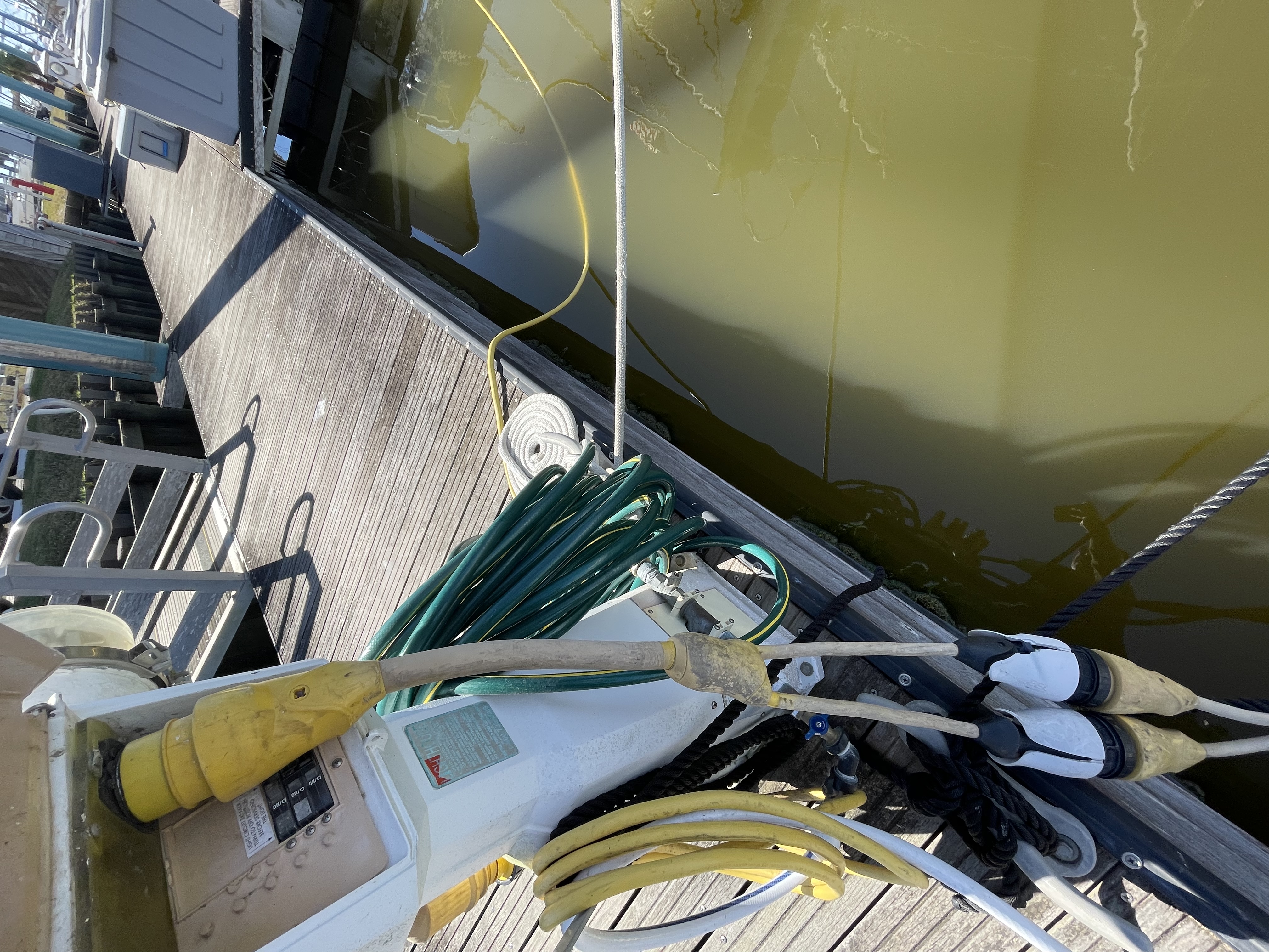
@Kevin Windrem In this photo that Dani posted. I too have a similar setup on my boat where the 50 amp cable goes into a splitter that plugs two 30 amp sockets into my boat.
Also these two legs that go into the boat end up at a 3 position rotary switch. It has 3 positions: Shore 1, Shore 1&2, and Generator which has NO breakers, but is a break-before-make switching setup. From that switch, it breaks the lines into the two lines to the two AC distribution panels which each have a breaker. This is how my boat came from the factory.
Should I wire the Multiplus into the 3 position switch or after the switch? Or after the circuit breakers (which would require me splitting the neutrals out again)?
I have had several people look at it who are "arm chair" boat mechanics/electricians who predominately work on small outboard boats that say I should put in a new sliding, break before make breaker switch panel (which is expensive). It would also require me reworking my entire panel. But If my boat already has the rotary switch, can I still not use it?
Thanks for your time in advance. :-)
Technically, the neutrals are tied together in this case, but with two shore power cords this might not always be the case.
Even if the neutrals are tied together at the source, there could be different resistances resulting in unbalanced neutral current. If both legs are on the same phase, then the imbalance could overlooad/overheat one of the neutral conductors.
The worst case scenario is if one of the 30 amp single phase shore power sources has reversed polarity (hot on the neutral). Sparks will fly, cables will melt or worse since generally neutral conductors have no circuit breakers.
The original design keeps hots and neutrals separate from the shore power cords all the way to the distribution panels. That is the way it needs to be with everything in between. So a Multi 120x2 is out of the question because it relies on a 120-0-120 power source, not two separate 120-0 sources.
Another consideration: any 240 volt loads connected between the hots of the two shore power cords could back feed 120 volts from one cord to the other. You probably don't have this situation and if the distribution panels are truly separate this wouldn't be likely but ...
If you want to do something that is not to national and local codes, you are on your own.
Thanks for your help... Everything on the boat is 120v. Nothing is 240v. That is why I bought the Multiplus II. Assuming it was the correct choice for 2 separate 120v lines.
It seems like at a minimum, it would be a good idea then to add a circuit breaker prior to the rotary switch on my boat on each of the two incoming power lines. Would you agree?
I have already purchased the Multiplus II 120x2. So I would like to use it as more than just a battery charger.
I have seen some people deal with this issue by just powering L1, since it will bridge output power to L2 if there is no separate input power to L1. I realize that this would limit the power in and out, but then I am not wasting half of the functionality of the unit.
If I connect the L1 input to just one input leg of the incoming AC (30amps max) and the outputs could go to each of the two AC distribution panels with the max volt/amps not exceeding the limit of the one line. Are my assumptions correct? Or as I think about it, it seems I would still have the potential of L2 Neutral being out of phase, if L2 Neutral from the inverter/charger is out of phase with the L2 Neutral plugged into the boat.
So would I just have L1 plugged into the AC IN on the Multiplus II and have the AC OUT going to the one AC panel and leave the second AC panel out of the circuit?
My rotary switch is rated for the two separate 30 amp circuits and the generator part is rated for the 50amps from the generator. Looking at my boat, there are only 3 lines coming from the generator, a L1 (hot), a Neutral and a Ground that goes to the AC Panel 1, and there are jumper wires that go from these lines to the second L2 (hot) and the other Neutral (tied together) on the rotary switch contacts that feeds the second leg of the switch back to the other AC Panel 2. Again this is all factory installed. This would seem (clearly) that these are clearly using common Neutrals as well on the generator side.
Would you give me the "Reader's Digest" on how I can us the Multiplus II in my situation, and what else I might need to add to make it work (if even using 1 leg L1). Thanks again for your time.
Good morning. How did you solve this issue Dani Pennington? I have a similar setup with dual incoming 30A GFCI circuits to my Jeanneau sailboat on a 50a y-splitter at the dock pedestal.
@stephen-dawes Did you get an answer? I am interested in this topic as well?