question

impatient avatar image
impatient asked

Switching MPPT 100/20 output between two separate battery banks

I have read: https://community.victronenergy.com/questions/92306/1-mppt-controller-with-2-power-banks.html and some others but still have questions, especially since one battery bank will be LiFePO, and the other AGM ( both nominal 12v):

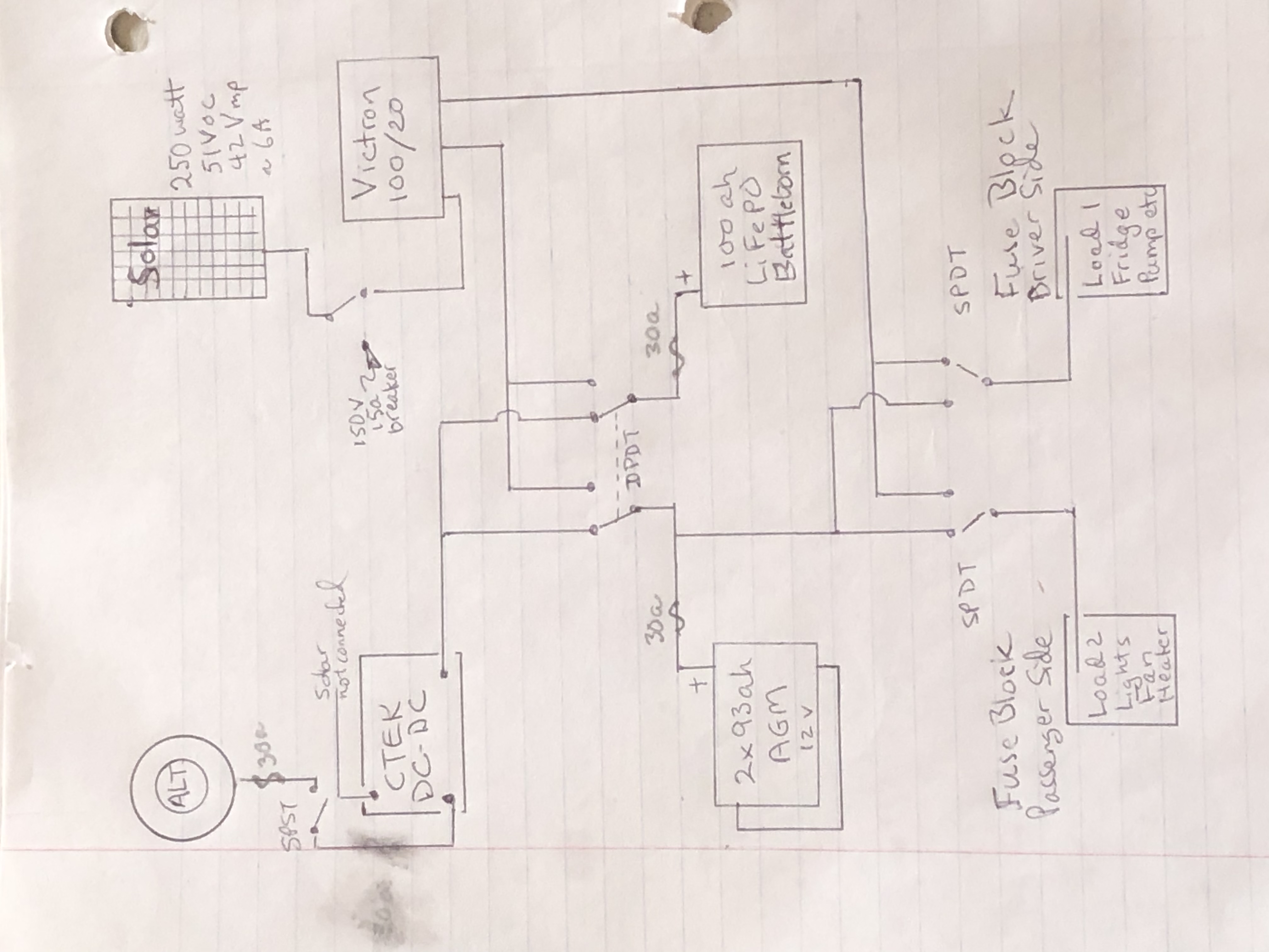
if I have an external switch connected between a 100/20 MPPT controller and the batteries, can a load or controller, or battery be damaged if I switch the battery to “off” while there is solar input? Actually, the purpose of the switch is to redirect the MPPT’s output between 2 separate battery banks. The banks are never joined. The interrupt would “normally” be momentary, as the switch passes between connection from one bank to the other. I also would have a disconnect switch between the solar and the controller, but human error might come into play, and the solar not get disconnected every time I switch between battery banks. If it matters, solar voltage would be approx 50-55Voc, and PV amperage low at approx 6a. Also, I had intended to connect loads to the controller’s Load outputs…but this is not mandatory.

Is this safe if 1) always disconnect solar while switching the output, or 2) doesn’t really matter if for relatively short durations, or 3) never safe at all?

***related, the thread referenced above ended with ”Mike” recommending connecting the 2nd battery bank to the load outputs of the MPPT (100/20 in my case). This might have some advantage, though without having the unit and manual in front of me to try this, I don’t know if that is really a feasible and safe approach. The downside of using an external switch is a) the MPPT’s logging stats will get confused, and b) since one bank is AGM and the other LiFePO, the charge profile will not be optimal for both without further monkeying around from a smartphone each time (NOT desirable).

further info: currently, I have 160w panel, a Morningstar PWM solar and CTEK DC-DC charger with built in MPPT for solar, and both battery banks are AGM. I switch which controller is attached to which battery without issue (I think…I’ve had this for 3 yrs.). The LiFePO is new, replacing one AGM bank, but 2nd AGM bank too good to throw away. The 250w 55voc panel has yet to be installed (currently 160w, ~22voc), and the Victron MPPT has not even been ordered yet. All negative leads (which not shown on diagram), are bonded together at one common point. It might make sense to NOT share that bond with the new higher voltage solar negative lead…but run it ONLY into the Victron MPPT.

I am open to other suggestions, but this mimics current set up, which has been working (caveats on voltage and chemistry differences).

3ccbcb3e-8374-475c-9155-d5f8771fe17f.jpeg


MPPT Controllers
2 |3000

Up to 8 attachments (including images) can be used with a maximum of 190.8 MiB each and 286.6 MiB total.

5 Answers
kevgermany avatar image
kevgermany answered ·

Suggestion.

Direct all charging towards the AGM bank.

Add an Orion DC:DC to charge lithium from AGM. You existing DC:DC may be suitable.

This eliminates input switching.

Whn e you replace the AGM batteries consider a single bank and eliminate switching completely.


2 |3000

Up to 8 attachments (including images) can be used with a maximum of 190.8 MiB each and 286.6 MiB total.

impatient avatar image
impatient answered ·

I appreciate your answer Kev. Where would loads be handled? Only from AGM?

my approach would have been to run loads off Li while asleep…which would be only a small 15-25% dent in its SOC. In the morning, brief charge of AGM to get them freshened up a bit (which could even be off the DC-DC), then full charge of Li (which should take 2hrs if sunny, maybe 3hrs max), followed by AGM full charge (or as good as possible), running loads off AGM all day while charging and evening/night until bedtime…so they will be less than 100% overnight...maybe 60% SOC, but could start using Li earlier if needed. Of course, all this changes if heavy overcast, or up in the woods all day. The one thing is I’ve read Li is better for PSOC (partial SOC) usage, and I really don’t know how chargers / batteries react when absorption or float is constantly interrupted by fridge cycling For either chemistry.

Single battery bank has its appeal. Yes, it would be nice to not have to worry about switching. But emergency replacement while on a trip is the most dreaded. I’ve lived full-time in this van for upwards to 3 months at a time.

1 comment
2 |3000

Up to 8 attachments (including images) can be used with a maximum of 190.8 MiB each and 286.6 MiB total.

Sarah avatar image Sarah commented ·
@Impatient another problem with your design is the need for different settings on the MPPT for the different battery chemistries. If emergency replacement is your your concern I would tend to run the lithium batteries full time (if possible) and keep the AGM charged using a small dc-dc charger as a backup. Main reason for preferencing the lithium batteries is that they charge faster (making maximum use of limited sunlight) and cope better with partial state of charge.
0 Likes 0 ·
j-mac avatar image
j-mac answered ·

So I have been pondering the same question for the same reason, because it would seem to me that deep cycle batteries would prefer not to float if they're not going below 20%.

so my thought was that they would be happier to run their full cycle of 40% and then get their full charge, but I wanted to make sure I always had a fully charged battery ready to go in case the sun wasn't shining at the time that the swap would occur.

after a lot of research in the last few weeks I've concluded that it would still have to be somewhat of a manual task, and the only thing i can see that would help are these pretty robust switches that they use for main disconnects on home installations the cheap ones being $22 and going up to $100.

There's also a four pole breaker for $60

the A/B selector switches commonly used in marine applications only switch one side of the feed (positive), and so I was looking for a switch that would switch both positive and negative, and the disconnect switch I'm talking about switches four poles at the same time, meaning four in to four out, and so I'm planning on having two of the lines be from the PV array to the charge controller, and the other two being from the charge controller to the battery, that way there would only be one switch to turn, ensuring that I would never forget to turn off the one from the PV array first, because they would both be switched at the same time. then I would just manually swap out the batteries by connecting some wires and then turning the switch again.

Since the charge controller is really the only thing that I have grounded to the vehicle I think that would handle any residual power rot so the controller wouldn't be damaged, of course I have yet to try this out but it should be any day now.

also I don't think it would work with two different types of batteries unless you divided your PV array into two as well . i guess you'd end up with two separate systems,

You could have a switch to just use one inverter.

I feel like at some point someone's going to design this dream circuit of mineb Schumacher makes a three-bank sequential charger, but it's 120 volt AC and so if that could be incorporated into an MPPT charger that would be awesome, I wish I knew everything needed to be able to design a circuit like that. Maybe someone will read this and do it and send me one for free.

One helpful hint I learned was putting a spade connector on the end of the wire for those heavy gauge screw terminals.

even with all the advertised protection that the mppt chargers claim to have, I think they're still very sensitive, and that's why there's so many bad reviews because people are not fully understanding the instructions before they make the connections, and most of the instructions are not very clear at all so I don't really blame them.

2 |3000

Up to 8 attachments (including images) can be used with a maximum of 190.8 MiB each and 286.6 MiB total.

mvas avatar image
mvas answered ·

@Impatient Impatient wrote ...

... Actually, the purpose of the switch is to redirect the MPPT’s output between 2 separate battery banks. The banks are never joined ...

Actually, the two battery banks are always joined, via the DPDT switch.
Why do you even need the DPDT switch?
The entire "switch" design is bizarre.
I doubt that the MPPT 100/20 can power those loads without a Battery Bank connected.

2 |3000

Up to 8 attachments (including images) can be used with a maximum of 190.8 MiB each and 286.6 MiB total.

impatient avatar image
impatient answered ·

Well, it’s possible the diagram doesn’t perfectly reflect the physical wiring and/or you don’t understand the switching concepts. I can virtually guarantee (tested with volt/amp/ohm meter) that the two batteries are not electrically “connected.” I’ll explain what a DPDT is and does if requested, but short answer is each side is isolated from the other. One side corresponds to the LiFePO, and the other side the AGM(s). The position of the lever determines which controller each battery is connected to. When one battery (eg LiFePO) is connected to the Victron, the other battery (eg, AGM) is connected to the CTEK. And vice versa. And yes, There is a middle “off” position, with nothing connected, and therefore no charging and no loads, Both batteries are never connected to the same controller, and both controllers are never connected to the same battery. That’s how DPDT switches work.

the SPDT switches in the lower part of the diagram, are not “ganged“ like the DPDT, so both fuse blocks can be attached to either battery, or can be “split” with one battery powering one fuseblock, and the other battery powering the other fuse block. Again, tested, but the fuse blocks are not a “back channel” capable of connecting the two batteries to each other; neither fuse block can be connected to both batteries simultaneously.

conceptually, this has worked for 5+ years. I have reworked it this year to use better fuses (and get rid of the cheap Amazon (or eBay) inline fuses. One of those failed completely (melting in a way that allowed an un-fused low-amp connection), and 2 others were beginning to melt, but hadn’t caused an identifiable problem yet. I replaced the one that completely failed with a better one, and everything worked again as planned.


2 |3000

Up to 8 attachments (including images) can be used with a maximum of 190.8 MiB each and 286.6 MiB total.