question

mattw avatar image
mattw asked

Parallel connection to Multiplus II from Feed. not series.

i havent bought one yet.

i just need to understand the granular connections if i do go for this. i've read and watched lots of youtube, but can't quite find the practical answers i'm looking for, from the standard wiring diagrams i've seen.


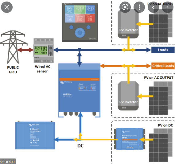
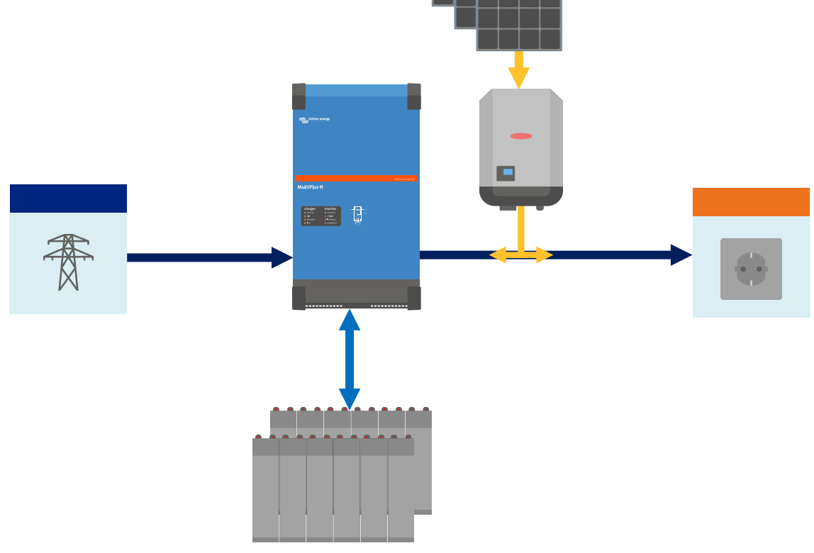
i'm thinking of using it as an ESS in my home. just for storing electricity in the batteries as a UPS.


i'm in the UK. in the countryside. 230v. occasional power outage. - it's annoying when it happens.


electricity comes in from the street,
into the detached garage through the wall,
into the 100a fuse,
then into the smart meter,
then into a (hardly used) consumer unit (lots of spare ways), before going out of the garage, under the driveway to the house where there's another consumer unit for the house etc.


i dont want the multiplus connecting in series between the smart meter and load. is this possible?


i would call this a parallel connection to the electricity backbone. from my basic knowledge of electricity.


do we just take a 32a RCB/MCB Live wire from the consumer unit into the multiplus "AC-IN-1 L" terminal.
and then from the "AC-IN-1 N" back to the the relevant common neutral in the consumer unit.


is that all i have to do?

(of course batteries need to be connected , and rest of the software setup eventually).


or do i have to connect "AC-OUT-1" terminals to somewhere in the consumer unit?

i'm assuming so, but how do i get the powerassist AC-OUT-1 output back into the backbone of the house, and thus out to the house?


thanks, hopefully i've made it clear enough :)


Multiplus-IIESSsetup
2 |3000

Up to 8 attachments (including images) can be used with a maximum of 190.8 MiB each and 286.6 MiB total.

5 Answers
wkirby avatar image
wkirby answered ·

As a UPS type system you need to take the loads out from AC-OUT, a series configuration with theMultiPlus between the smartmeter and the load.
Power goes in to AC-IN and is passed through to AC-OUT. When the network is unavailable at AC-IN then it will disconnect and AC-OUT will continue to provide power from the battery.

2 |3000

Up to 8 attachments (including images) can be used with a maximum of 190.8 MiB each and 286.6 MiB total.

Kevin Windrem avatar image
Kevin Windrem answered ·

Victron inverter/chargers are set up to pass the grid power through them to the loads they supply: Grid to AC IN, AC OUT to distribution panel. That is the only way they will work.

The Multi has an AC input relay that connects the grid to the inverter/charger core when grid power is within usable values (voltage and frequency). The inverter/charger core is connected directly to the AC output(s).

In normal operation, the AC input relay is closed connecting the grid to the loads with the inverter/charger core charging the batteries or assisting the load when grid isn't sufficient.

When the grid falls out of acceptable values, the input relay opens and the inverter/charger core immediately begins supplying power to the loads from the batteries.

For redundancy, an inverter bypass transfer switch is recommended that would route the grid power directly to the loads. This allows the inverter to be shut down for maintenance.

While connected to the grid, the voltage and frequency of the grid appear at the Multi's AC output. In situations where the grid power isn't stable enough for the loads it feeds, separate battery charger and inverter should be used. In this case, the grid feeds the charger keeping the batteries topped up and the inverter powers the loads from the battery. In normal operation both the charger and inverter are subjected to the load power 100% of the time. The benefit of such a system is the voltage and frequency supplied by the inverter are independent of the grid. Boats somethimes use this system so they can accept 120 volt 60 Hz or 230 volt 50 Hz shore power and still run motors, etc the rely on a specific frequency of AC power..

2 |3000

Up to 8 attachments (including images) can be used with a maximum of 190.8 MiB each and 286.6 MiB total.

Rob Duthie avatar image
Rob Duthie answered ·

Hi

You can run them in parallel mode with the grid, and have a AC1 feed the critical loads and the AC2 to other non critical loads, so you can still export surplus power as well with a AC coupled PV inverter.

You can also wire in a change over contactor as well, to supply all the loads if required.

This is what is have done with my test system.

2 |3000

Up to 8 attachments (including images) can be used with a maximum of 190.8 MiB each and 286.6 MiB total.

mattw avatar image
mattw answered ·

@Rob Duthie

thanks for your repl(ies). we only have one Load, and that is 'the house' there are no significant loads in the garage, just a fat cable going out of the garage to the house, so AC-OUT-2 is redundant, for us.

have you got a granular and detailed circuit diagram?

if you look at the typical circuit1.png below - i keep seeing similar to this everywhere online.


circuit1.png


ignoring the orange 'critical loads' - n/a.


this looks like the blue victron inverter is connected in parallel. that doesnt look like a multiplus to me, so is this possible with the multiplus II ? i'll assume it's a multiplus for this post.


this diagram isn't detailed enough for me.


the blue arrows going to and from the top of the multiplus: does this represent two Lives and two Neutrals? one going to the AC-IN-1, and one going from AC-OUT-1 to the BLUE Loads/the backbone (as i would call it).


so i connect AC-IN-1 from the henley blocks (there's some henley blocks between smart meter and CU, one Live, one Neutral) and connect back to the backbone by running from AC-OUT-1 back to the henley blocks?

would this represent the blue arrows notation above the victron multiplus? do you think


circuit1.png (91.9 KiB)
3 comments
2 |3000

Up to 8 attachments (including images) can be used with a maximum of 190.8 MiB each and 286.6 MiB total.

Rob Duthie avatar image Rob Duthie commented ·

This explain a lot document

Presentation - ESS systems.pdf

0 Likes 0 ·
Kevin Windrem avatar image Kevin Windrem commented ·
In the circuit1.png drawing the blue Loads box are connected to the grid and the PV inverter. The Multi would feed energy into this node which would be destined to the grid (aka "feed in"). In this configuration, I'm not sure the Multi would supply any energy to the blue Loads box. Certainly, if the grid is not present, the blue Loads would NOT be powered.


Only the orange Critical Loads (aka Essential Loads) receive power from the Multi when there is no grid power. So those loads need to be connected to the OUTPUT of the Multi.

Most of the models in the Multi family have a second AC output. AC 1 out feeds Critical Loads, AC 2 out could feed noncritical loads (similar to the blue Loads box). AC 2 out is configured to disconnect when the grid does.

These drawings are simplified to show concepts not the details of hot, neutral and safety ground connections. This is because the number of hot legs, the number of Multis and many other factors confuse the conceptual drawings. The manuals often provide diagrams that do show the details, including drawings for multiple phase systems and multiple Multis in parallel to each other.

The ONLY connection that can connect to the grid connection terminals are the INPUT to the Multi and potentially a grid-connected PV inverter. There is usually a box fitted with breakers for each connection (Grid, Multi, PV inverter) that then connect to a common point. As shown in the diagram, you usually need a "grid meter" that monitors power into and out of the grid. The GX device controls the Multi and PV inverter to regulate how much power is fed into the grid or pulled from it. To limit grid power usage, the system then pulls power from the battery connected to the Multi and/or the PV inverter. But again: no grid = no power to the blue Loads box because the AC input relay inside the Multi will be open in this case, isolating the inverter core from that common point which includes the grid.

In this context, "Multi" could be one unit, multiple units configured for two or three phase power or multiple units connected in parallel to each other to increase the inverter power available, or a combination of both. "Multi" could also be "Quatro" inverter/chargers which are essentially higher power Multis.

If you are still confused, I highly recommend hiring a company familiar with Victron inverter/chargers and Energy Storage Systems. This high powered equipment must be connected and configured properly to be safe and prevent hazards.

0 Likes 0 ·
wkirby avatar image wkirby ♦♦ commented ·

DO NOT EVER connect AC-OUT to the Henley blocks, directly or indirectly!

For UPS functionality, critical loads (orange bit) is applicable, we should not ignore that. That is the part where you connect your house to.

Those ESS example diagrams that you are looking at are causing confusion. Those are grid parallel examples and are not applicable for your application.
You want something like this, ignoring the PV panels and inverter of course. Blue is grid connection to AC-IN, orange is critical loads from AC-OUT:
1645948288646.png

Simply make a connection from a dedicated circuit in the garage CU to AC-IN of the MultiPlus.
Disconnect the cable which goes to the house from the garage CU panel and connect it to AC-OUT of the MultiPlus.

0 Likes 0 ·
1645948288646.png (30.6 KiB)
mattw avatar image
mattw answered ·

thanks your replies, everyone. the fog is lifting. which is awesome, because i have to understand it as i'm the one who has to debug it if it goes wrong some day in the future.


i'm thinking multiplus's are meant to be connected in series between the feed and the load. like you say @WKirby the design should simply move the connections to make it go in series.


this is just a thought in my mind. and i may be comparing apples and pears here wrongly. my friend has a LuxPower hybrid inverter - batteries and solars going directly to it. it's definitely connected in parallel, because if you press the RCD test button it powers down audibly and says 'Grid Disconnected' (presumably getting its power from the batteries to tell us this).. and the house lights stay on and everything else. tracing the tails cables back to the Henly Blocks, it's definitely connected in parallel. - but it does feed the house.


from what i've read that lux is a 'grid tie' ac coupled inverter?? would you agree. so is the multiplus a different class of device? is it because the multiplus creates a Micro Grid when the grid goes offline? keeping other pv ac solar inverters running?


thanks @Rob Duthie - really good presentation. lots of considerations for my design.


i'm thinking i'm going to have a multiplus in series with the house load. and then have a pv dc solar with MPPT, into the batteries distribution bar. which sounds really simple now, but it takes a lot for an amateur to get to that final design, eliminating unnecessary things. i may have micro managed this too much, but it's been interesting to learn about a new technology. haha.


i'll post my final wiring diagram, for others to read, when i've drawn it up. it might help someone some day.


1 comment
2 |3000

Up to 8 attachments (including images) can be used with a maximum of 190.8 MiB each and 286.6 MiB total.

wkirby avatar image wkirby ♦♦ commented ·
A grid parallel system like you describe with the Lux inverter is able to power the house from batteries, but only if the grid AC is available. Sure, the inverter its self stays in standby, powered from the battery, but it would no longer be inverting and powering the house. Indeed, the circuit breaker is open and there would be no AC coming out of that inverter with its circuit breaker open. At that point the house is being powered solely from the grid.

The Victron systems can also be configured this way, powering the house from reverse power via AC-IN and this is a grid parallel system. If the grid power fails, the inverter will disconnect and no more power would come out of AC-IN. If it did, then it would be trying to energise the grid, both impossible and dangerous.

In summary, any grid parallel system must disconnect when its AC input fails and the system must have permission to operate from the DNO.

0 Likes 0 ·