question

captkrisp avatar image
captkrisp asked

ESS DC coupled feed-in multiple solar chargers (solved)

Solved: see "Update3" post below from Jan 9, 2022.

------ original post content ------

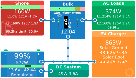
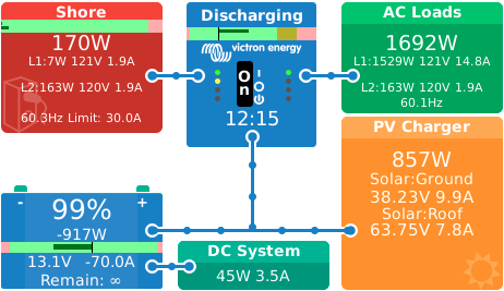
I have 2 solar charge controllers (Victron 100/50). With DC-coupled feed-in enabled, only 1 of the charge controllers is supplying feed-in power.

Does anyone know how to make both charge controllers feed excess power to loads?

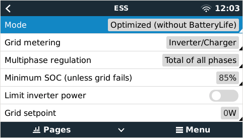
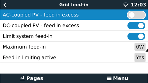
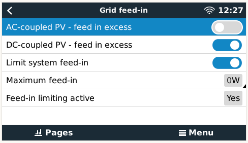
This system is installed in an RV so back-feeding power to the grid isn't desired, therefore I have set the Max feed-in to 0W. The RV has an auto-transfer switch on the shore-power feed so there is no possibility to back-feed power to the shore cable when disconnected.

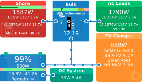
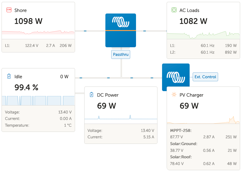
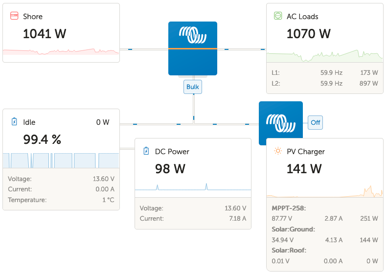
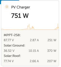
The "Solar:Roof" array is 2x350W panels and the "Solar:Ground" array is 1x350W panel. Here are some screenshots.
1640118366504.png

1640118402880.png1640118429050.png

ESSMPPT SmartSolar
1640118366504.png (82.3 KiB)
1640118402880.png (18.7 KiB)
1640118429050.png (27.2 KiB)
2 |3000

Up to 8 attachments (including images) can be used with a maximum of 190.8 MiB each and 286.6 MiB total.

5 Answers
captkrisp avatar image
captkrisp answered ·

Update3 (the resolution):

After much playing and testing, I have identified the resolution to this issue.

Under DVCC, enable SVS (Shared Voltage Sense).
1641758153017.png
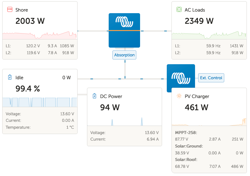
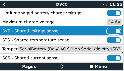
As you can see, I have also enabled SCS (Shared Current Sense) but I don't think this is a key config.

It has been a little over 1 week since I enabled SVS and since then both solar chargers function as expected.

ESS Mode is now "Optimized (without BatteryLife)" and the system performs as I expect it should.

(It might also interest people to know that I had re-enabled VE.Smart Networking on the BMV-712 and both solar chargers. So the lesson with this is that VE.Smart Networking does not cause a problem for ESS controlling multiple solar charge controllers as some people have suggested.)

Here are my current ESS configs:
1641758590680.png1641758636033.png


The only annoying quirk is that shore power (installed in RV) seems to almost always supply the full power to the L2 load (split phase input) while the solar chargers will supply power to L1 and battery.
In this screenshot you can see that the PV Chargers are supplying 577W to battery, 49W to DC load, 214W to L1, and 20W presumably to inverter. While shore power is supplying 160W power to L2 only.
1641758780476.png


With an electric heater switched on you can also see that the solar chargers and battery are providing all power to the L1 AC loads, while shore power still provides the L2 power only.1641759320017.png

This is also seen when the heater is moved to L2.
1641759614823.png


Hopefully this information will help someone else.

This inverter is the MultiPlus-II 12/3000/120-50 2x120V


1641758153017.png (33.2 KiB)
1641758590680.png (30.6 KiB)
1641758636033.png (27.2 KiB)
1641758780476.png (50.3 KiB)
1641759320017.png (51.6 KiB)
1641759614823.png (51.1 KiB)
2 |3000

Up to 8 attachments (including images) can be used with a maximum of 190.8 MiB each and 286.6 MiB total.

David avatar image
David answered ·

Feed-in refers to feeding the power to the grid, not loads. If you don’t want power going to grid, disable both Feed-in options.

The DC MPPTs will power loads as long as battery is in a charged state. (You have the option to keep batteries charged enabled - so MPPTs will charge the battery till they are).

2 |3000

Up to 8 attachments (including images) can be used with a maximum of 190.8 MiB each and 286.6 MiB total.

captkrisp avatar image
captkrisp answered ·

Thanks for your reply David.

Your description of how the feed-in is intended to work has been changed to allow not only limiting how much power is fed back to the grid but also disabling with 0W. (I saw this on a Victron video somewhere recently).

Here is a screenshot showing solar charge controllers providing only the amount of power the battery (and DC loads) will accept when feed-in is disabled:

1640125797984.png

And again with feed-in enabled and limited to 0W:

1640126446331.png

Notice the reduced power from Shore compared to AC Loads.

Due to the Solar:Ground array angle and orientation to the sun, which has a higher angle than that of Solar:Roof, it almost always produces just over 50% (instead of at or under 50%) of that which is produced from the roof array. So the image above is expected to have a much higher output or at least something from Solar:Ground.

Here the Solar:Roof array has been disconnected so it can be seen that the Solar:Ground performs as I stated.
(thicker clouds passing by so power output is reduced)

1640126833749.png

And again with Solar:Roof connected we see that Solar:Ground maintains the "selected" charge controller instead of both charging.
1640126958629.png

Any other ideas that might help?


1640125797984.png (80.2 KiB)
1640126446331.png (78.6 KiB)
1640126833749.png (75.0 KiB)
1640126958629.png (79.7 KiB)
1 comment
2 |3000

Up to 8 attachments (including images) can be used with a maximum of 190.8 MiB each and 286.6 MiB total.

David avatar image David commented ·
Not sure where you saw that, but the behavior with dc feed in disabled is that the MPPTs will ramp up to cover AC loads, but no higher.
0 Likes 0 ·
captkrisp avatar image
captkrisp answered ·

Update:

After removing the BMV-712 and both solar chargers from VE.Smart networking (some other posts suggested doing this, but initially had no effect on my system and may or may not be a factor but I'm leaving it disabled for now), physically swapping solar chargers connected to the other panel arrays, and hence roles (Solar:Roof became Solar:Ground and vice-versa, the Solar:Ground charger had a lower sequence serial number and it seemed to always be picked as the "primary" charger when I wanted the Solar:Roof charger to be the primary), and a few "random" manual disconnects of panel arrays from controllers as well as a few Venus OS reboot cycles, both solar chargers are now supplying power to the system as expected.

1640201930161.png

(Rainy and overcast day so power output is not optimal)

I have no idea which step(s) caused the system to begin working properly. It just started working. So at this time I will leave system configured as is for a while to see if all remains well.


1640201930161.png (19.1 KiB)
2 |3000

Up to 8 attachments (including images) can be used with a maximum of 190.8 MiB each and 286.6 MiB total.

captkrisp avatar image
captkrisp answered ·

Update2:

After a day of cloudy weather the solar charge Solar:Ground again stopped feeding power into the system.

2 |3000

Up to 8 attachments (including images) can be used with a maximum of 190.8 MiB each and 286.6 MiB total.

Related Resources

MPPT product page

VictronConnect manual

PWM or MPPT

MPPT calculator

MPPT codes

Additional resources still need to be added for this topic