question

flagunman avatar image
flagunman asked

Shared neutral 3 multiplus 2 10kva

Hello,


I have 400v 3 phase service at my residence. (230v line-neutral) I do not have any three phase loads. I have simply balanced the single phase loads across the three phases.


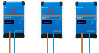
I would like to hookup 3 multiplus 2 10000VA inverters across the three phases. However, with my primary concern being redundancy, I do not want to synchronize them as one unit failing would bring down the whole system.


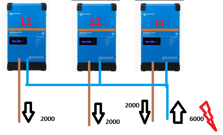
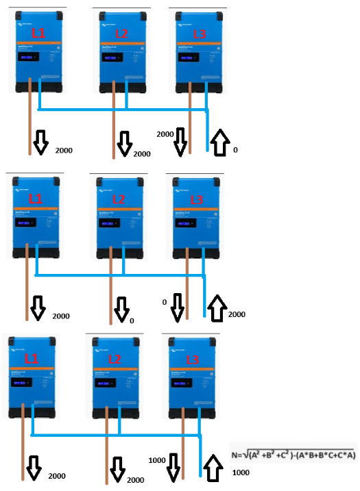
So, would it damage anything to hook all three unsynchronized units to the same neutral bar? I assume they would be synchronized when utility power is available as they would match the incoming power. When the utility switches off, they might drift from 120 degrees out of phase but that shouldn't matter without any 3 phase loads correct? Each unit would have its own seperate battery, mppt, panels, cerbo gx, touch 50, etc.


I can't seem to find a reason that this wouldn't work. Thanks for your help.

Multiplus-II
1 comment
2 |3000

Up to 8 attachments (including images) can be used with a maximum of 190.8 MiB each and 286.6 MiB total.

duivert avatar image duivert commented ·
advice: dont! its dangerous and the system is not designed for it
0 Likes 0 ·
8 Answers
janieronen avatar image
janieronen answered ·

Interesting setup as never seen exactly similar installation. What I would be first checking is to check are you allowed to install one-phase inverters that size to the grid. That's not permitted in some countries and specially if you are planning to feed in.

One issue can be with your installation neutral cable sizing as without symmetrical 3-phase currents are not balancing out. That is true even no three phase loads.


Anyhow with that special idea I would keep all loads also separated and act as three separate electrical systems as in example IRCDs etc may not work properly with out of phase situation.

2 |3000

Up to 8 attachments (including images) can be used with a maximum of 190.8 MiB each and 286.6 MiB total.

delf67 avatar image
delf67 answered ·

As Janieonen said, I would keep the three output neutrals separate. They would obviously be joined at the AC in when mains/ grid is present, but would be three separate systems when inverting. I don't actually think it would be a problem to join them, but it also wouldn't be needed so why bother?

2 |3000

Up to 8 attachments (including images) can be used with a maximum of 190.8 MiB each and 286.6 MiB total.

sharpener avatar image
sharpener answered ·

If they are not connected as a proper three-phase installation and the domestic wiring has a common neutral I think you will have trouble with their neutral-earth bonding relays because the three inverters will activate them at fractionally different times. The first one may be OK but the other two will then see that neutral-earth link as a fault condition.

2 |3000

Up to 8 attachments (including images) can be used with a maximum of 190.8 MiB each and 286.6 MiB total.

flagunman avatar image
flagunman answered ·

Thanks for the replies!


The primary reason for bonding the neutrals was laziness. The house is obviously already wired to common neutral. If common neutral is kept I just need to feed each phase with line out from the inverter and that's it. If I wanted separate neutrals I would have to go through the panel and find corresponding neutral wires to each branch and ensure it was connected to the same neutral bar. If anything was connected incorrectly the voltage across say l1 to n2 would be anything from 0v to 400v and the fireworks would start. I shudder to think what my fridge would do with 400v.


As far as location, I'm located in Zambia so codes are more guidelines and if you start looking around you will soon realize that everyone has thrown the code book out the window and common sense prevails (and even that seems to be in short supply among many "electricians")


I did think about excessive neutral current however with each inverter being rated for 100a (interior wiring/copper traces/connections are oversized) and it being a single household I simply oversized the neutal wires (and line in wires) to 35mm cable. I will occasionally check wire temps with my flir camera to ensure good operating temperatures.


That's an interesting point with the earth bonding relays. I guess that would depend on whether the inverter can sense if a ground connection has been made on the output and whether it bases is relay function on that sensor or simply the presence of ac in. If all that can happen is a warning and failure to provide power I will attempt it and update if it is feasible. I gave also put a help request in to victron but have not received any reply, not holding my breath. Thanks again for the valuable info. Anything additional you think of us much appreciated. Everyone needs something like this rattling around in their brain to ensure they don't get a full night's sleep.

2 |3000

Up to 8 attachments (including images) can be used with a maximum of 190.8 MiB each and 286.6 MiB total.

dognose avatar image
dognose answered ·

I think you have a fundamental missunderstanding there.

- When you run inverters unsynchronized, with a dedicated neutral, you have to rewire everything as the neutral and "Hot Wire" need to be connected in pairs.

1714027671929.png
- When you run inverters unsynchronized (i.e. all on "Phase 1 setting") with a common neutral, you are risking to highly overload the neutral connection, as all the return-currents of ANY Inverter will run through the same neutral back to the inverters - in the very same phase-shift!.
(This is your "lazy option"? Highly dangerous!)

1714027782579.png
- When you run inverters synchronized (three phase) you can use a common neutral by design. For symmetric loads, the current on neutral will be 0, for assymetric loads (only one phase) it will be maximum the current running through the loaded phase, in general the sum of all phases * angle of the phase.
1714028422318.png


Even if the inverters would probably run in "kind of 3 phase" mode, while Grid is present, they will inevitable drift oft in case of an grid failure. And then it is just a question of "bad timing" until they are running with the same phase-shift and a high load is present and finally overloading your (common) neutral.

This can be avoided by properly setting them up as a 3 phase-layout.

Nothing more dangerous than a "problem" that will eventually appear in 2 weeks or maybe 3 years. Murphy's law is typically stated as: "Anything that can go wrong will go wrong."

.... I simply oversized the neutal wires (and line in wires) to 35mm cable. ....

Please also have a look at: https://www.victronenergy.com/live/ve.bus:manual_parallel_and_three_phase_systems, especially the section

Warning against over-dimensioning the AC wiring


1714027671929.png (27.8 KiB)
1714027782579.png (31.0 KiB)
1714028422318.png (151.4 KiB)
2 |3000

Up to 8 attachments (including images) can be used with a maximum of 190.8 MiB each and 286.6 MiB total.

flagunman avatar image
flagunman answered ·

I appreciate the detailed information and agree with your assertions regarding a common neutral wire. However in my case, while I am "bonding" the neutrals, I am not "daisy chaining" the inverters as shown in your second photo. All inverters have a dedicated neutral wire that feeds back to the main panel. With all circuits carrying only what their breaker allows and all inverters regulating their outputs, there should be no way for excessive current to be present on any leg. Imagine your first photo but the wires just end at the same place (the neutral bar in the panel) which is where all circuits terminate. Because there is one common point with no daisy chaining I can't see that this would be a problem. Given that I have connected the wires as stated above do you see any issue? I agree that we should plan for the worst and hope for the best so feel free to assume all inverters are in phase for arguments sake.


As for the "oversized" wires I apologize as I used the wrong adjective. I would call the wire generously sized. With 35mm flexible cable being rated at 110a for transmission (longer lengths) the chassis wiring rating will be slightly higher. These inverters have a pass through capability of 100a so while 25mm cable would suffice, a more generous current rating would be beneficial for operating temperatures of cables especially if the proper protection devices are installed. Happy to hear your thoughts.

2 comments
2 |3000

Up to 8 attachments (including images) can be used with a maximum of 190.8 MiB each and 286.6 MiB total.

duivert avatar image duivert commented ·

" I am not "daisy chaining" the inverters as shown in your second photo. All inverters have a dedicated neutral wire that feeds back to the main panel. With all circuits carrying only what their breaker allows and all inverters regulating their outputs, there should be no way for excessive current to be present on any leg. Imagine your first photo but the wires just end at the same place (the neutral bar in the panel) "


sorry, but thats exactly what @dognose showed in his second picture!

0 Likes 0 ·
dognose avatar image dognose commented ·
Because there is one common point with no daisy chaining I can't see that this would be a problem. Given that I have connected the wires as stated above do you see any issue?

Hard to tell, without seeing the installation. I'm no electrican and generally wouldnt recommend anything where i'm not 100% sure that there are no side effects ;)

Beside of that "single" questionable point, you should also consider that having everything 3 times (batteries, gx, mppts, panels) is quite expensive and has drawbacks compared to a single system. (You cannot balance power between systems)

Compare all that vs the probability that a multiplus, years of experience in offgrid usage, really fails in case of an emergency.


0 Likes 0 ·
flagunman avatar image
flagunman answered ·

Also because this condition would only be present when utility power is not available (as this is when the phases would drift.) We can assume a max combined output of 24kW without getting into VA and imaginary power calculations. With voltage being 230v max current would be 105a. Which as specified is within specifications for 35mm cable.

2 |3000

Up to 8 attachments (including images) can be used with a maximum of 190.8 MiB each and 286.6 MiB total.

flagunman avatar image
flagunman answered ·

I will post my conclusion here for the next guy and to wrap up this thread. I contacted victron and my victron dealer and both said it would work as expected. I went ahead and connected things today and switched on. Everything is working well and the system is operating well.


Conclusion: Yes, this does work. Even though it is an uncommon practice, if the design considerations listed above are accounted for there is no evident danger in connecting this way. (As per victron and no one has been able to outline another reason). Even though everyone's first reaction is negative, it seems to be a knee jerk reaction and not one based on any legitimate reason.

2 |3000

Up to 8 attachments (including images) can be used with a maximum of 190.8 MiB each and 286.6 MiB total.