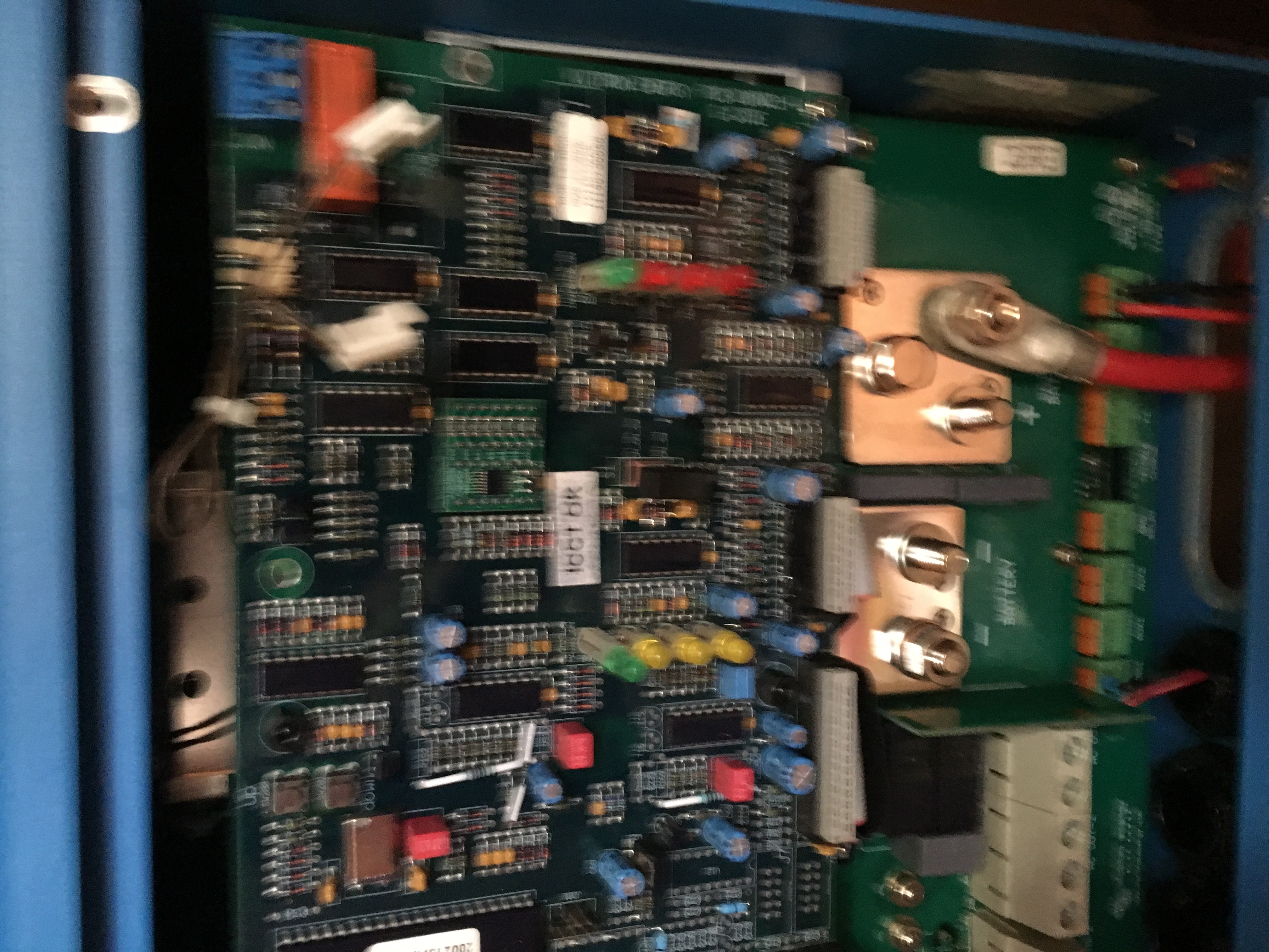
 Brown sensor wires are in fact not hooked up. The connectors don't seem to be compatible with the board
asked
immediate overheat
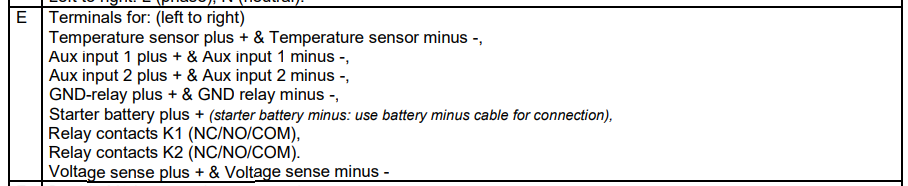
It looks like you have transposed the temp sense and volt sense connections.
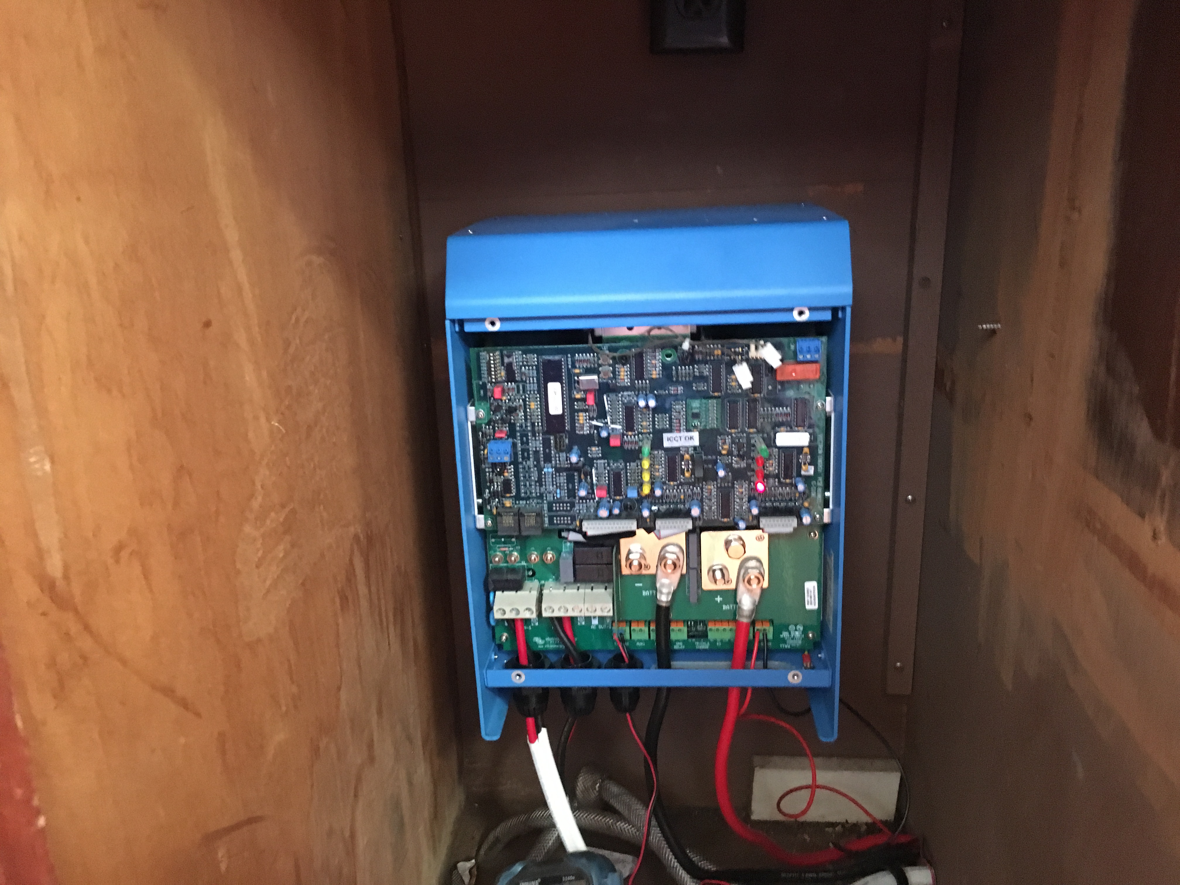
You also are missing an earth connection on the mains in/out.
Before going any further ensure that the the unit/wiring is properly earthed for safety! (best to get in a qualified electrician/installer)
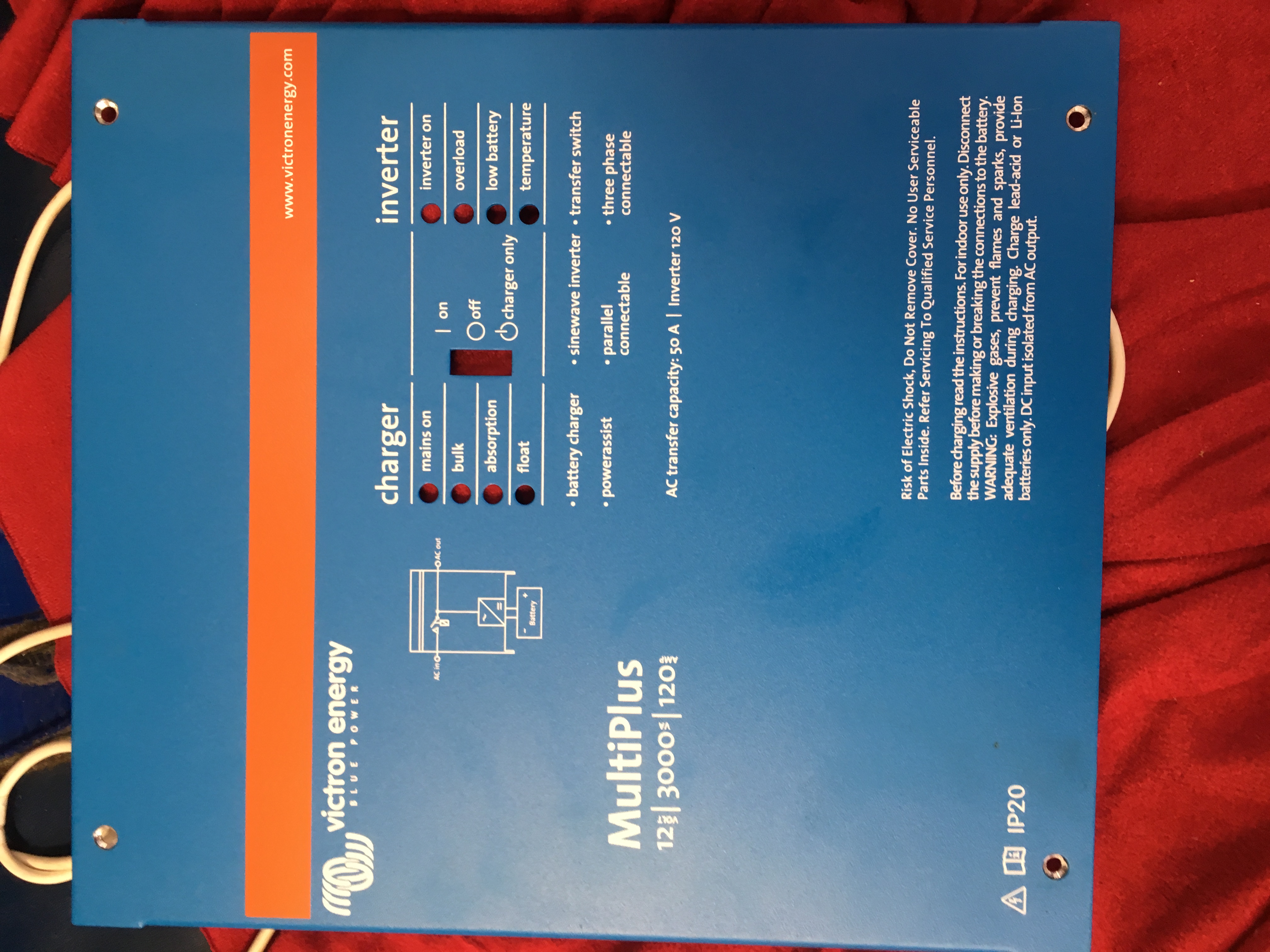
According to the related manual (Multiplus 120v 12/3000/120) it looks like you are using the correct terminals in the Multiplus for temperature sensor and the voltage sense wires.
Also confirm that the Multiplus temperature sensor is mounted to the NEGATIVE battery terminal (not the positive).
In my Multiplus (240v 24/3000/70) it has the brown wires at the top (I think they are brown but cant tell for sure with the photos that I have saved) connected to the nearby terminals on the PCB - see image below;
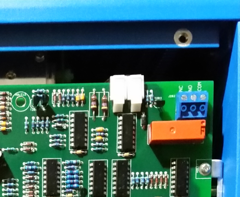
However, if the brown wires in your unit are not connected then I highly recommend engaging a Victron dealer / service agent to review your unit (rather than trying to reconnect them yourself). There may be a fault or other reason why they are disconnected...
The problem I'm having is that the unit comes on and the overheat light flashes three times and stays on. No pass through. No cooling fan, and no load. I checked this forum and found a like problem concerning the connectors for the internal temp sensors being disconnected. I had seen the two loose connectors before but didn't really know what they were for. I attempted to connect these wires but the plugs seem incompatible. Now I'm wondering if the PCB and the internal temp sensor harness matches. the socket on the PCB seems to be for a single four wire connector.
Yes, those connectors at the top 100% need to be plugged in to the board... this is the main control board for the whole system, and although I've never yet nailed down what exactly those two connectors do, I have absolutely established that the system doesn't work without them plugged in. Make sure your Multi is powered down and disconnected from all power sources, then connect both of those connectors (they do fit), then reconnect your power sources (including, as others have pointed out, making sure your earths/negatives are connected) and power the system back up. Pretty sure your problems will be solved.