question

johnjaymack avatar image
johnjaymack asked

How to get two or more outputs in the same order into a JOIN

Hi all,

I have two Victron MultiPlus-II 2x120 running in parallel. I am trying to automate some load shedding under certain conditions. For example, if I am connected to 50-amp split phase, I have around 9600 watts available. It is very possible to have the inverters providing Assist Power and everything works fine. But if we lose shore power, we can have the inverters trying to provide 5000 to 6000 watts. And they will do this for a very short time and then shutdown in protection mode.

I have placed some of my loads on the AC2 output which automatically sheds those loads when I lose shore power, but an unexpected overload is possible and has happened.

I am using the Victron Ve.Bus System Node to access some of the signals from the Multiplus for determining when to shed some output loads.

I have not found a single signal that gives me the Inverter Assist power, so I thought of doing the math and subtracting the Input Power phase 1 (W) from the Output power phase 1 (W). This seems to give me the inverter Assist Power. If Input Power is 3000 watts and Output power is 5000 watts, the the Inverter Assist Power should be about 2000 watts.

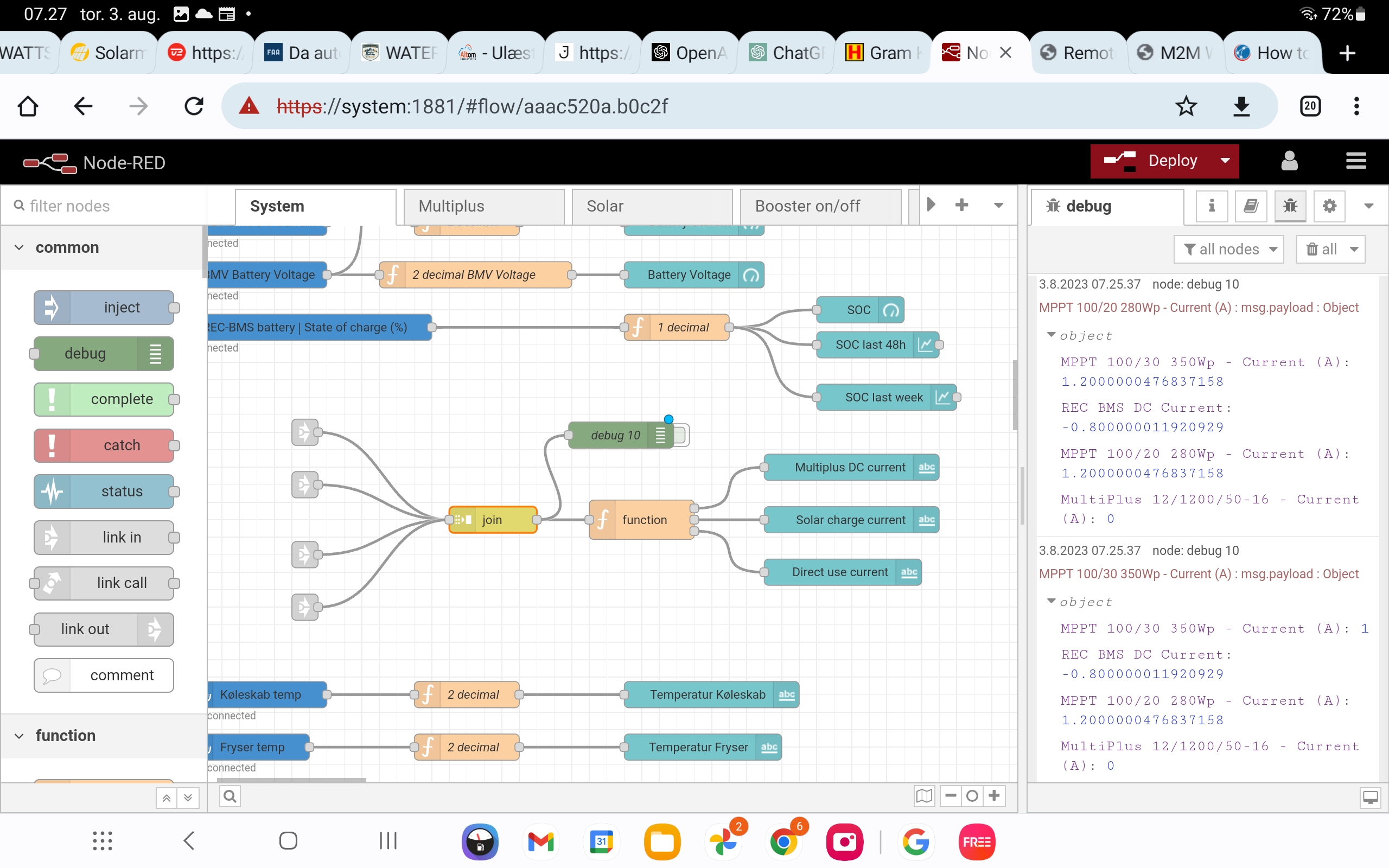
In operation, I find that the order of the signals from Ve.Bus Node will vary. Sometimes I get the Output Power first, then the Input Power, sometimes two Inputs, one Output, one Input, and then two Outputs, etc. In testing and monitor the math function, I see positive numbers, negative numbers, and zeros I have watched the outputs of the Ve.Bus Node and cannot see a particular pattern.

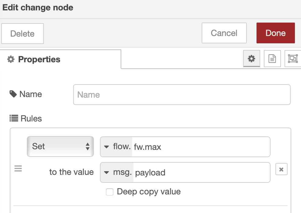
I have used a join node to get the two values, one from the Output message and one from the Input message and put them into an array, and then a math node to do the subtraction. But since the presentation of the information varies, I can get input - output, output - input, input - input, and output - output as an answer.

I have used a switch node to direct the information into two different directions, one for Input and a separate direction for Output, but I have not been able to figure out how to combine them into an array with a known position for each value each time so that the math node will give reliable results.

I am open to any suggestions, including that I may have gone up the incorrect path and that there is an easier method.


Node-RED
2 comments
2 |3000

Up to 8 attachments (including images) can be used with a maximum of 190.8 MiB each and 286.6 MiB total.

kevgermany avatar image kevgermany ♦♦ commented ·
@JohnJayMack

Moved to modifications space. You should get more success there

0 Likes 0 ·
johnjaymack avatar image johnjaymack kevgermany ♦♦ commented ·
Thank You


0 Likes 0 ·
14 Answers
nickdb avatar image
nickdb answered ·

There are different ways to do it.

I use change nodes to convert the msg.payload of an output node into a flow variable (that way they can also be referenced anywhere else in the flow).

I then use an independent function to add the flow variables together. This way it doesn't matter if they are out of sequence.


2 |3000

Up to 8 attachments (including images) can be used with a maximum of 190.8 MiB each and 286.6 MiB total.

Sten avatar image
Sten answered ·

You could also join them as a key/value objekt. Then you have a name for each value.

2 |3000

Up to 8 attachments (including images) can be used with a maximum of 190.8 MiB each and 286.6 MiB total.

johnjaymack avatar image
johnjaymack answered ·

@nickdb and @Sten, thank you for the answers. I still have some questions. First, I used a Change Node to Move the msg.payload to a msg.InputPower and to a msg.OutputPower message. I am not sure if that is what was meant. I am not sure what an "independent function" is exactly. I see that there is a Java Script Function node where I can add some JS. Is that the independent function that you referenced?

I am not sure what a "join them as a key/value object" would do. When I use the calculator node to do the math, I pass it an array from the Join node and it does the math. I am not that familiar with JS but from reading, it looks like I can use it to create an array which I can pass to the calculator node. Is this approach what is being suggested?

I really appreciate the help, and patience. Thanks

1 comment
2 |3000

Up to 8 attachments (including images) can be used with a maximum of 190.8 MiB each and 286.6 MiB total.

nickdb avatar image nickdb ♦♦ commented ·

For my method you must set the output to "flow" like so:

screenshot-2023-08-03-at-074335.png

The fw.max being the name you want to call it.

You can then use calls in a function to use it:

flow.get("name_of_variable") or flow.set() to change it.

Anything within the flow can make these calls and access the value stored.

The key method described below (or is it above) might be neater if you don't need to reference the data you are collecting elsewhere in the flow.

In the end it looks like:

screenshot-2023-08-03-at-075121.png

0 Likes 0 ·
Sten avatar image
Sten answered ·

As an illustration I have here one of my join node. It joins 4 different input into an object.

Then it do some calculation in a function node and output 3 diferent values.

All the input is comming in no particulary order, but it does'nt matter because of the key/value.

screenshot-20230803-072759-chrome.jpg


screenshot-20230803-072745-chrome.jpg


screenshot-20230803-072838-chrome.jpg


2 |3000

Up to 8 attachments (including images) can be used with a maximum of 190.8 MiB each and 286.6 MiB total.

johnjaymack avatar image
johnjaymack answered ·

Thank You so much. I have much to study now. I will digest what you have posted, and get back with a story of success, or a few more questions. I really appreciate the help.

2 |3000

Up to 8 attachments (including images) can be used with a maximum of 190.8 MiB each and 286.6 MiB total.

thebelcherman avatar image
thebelcherman answered ·

@JohnJayMack

9 months later and I'm running into the same exact issue. I've got like 2 weeks, of even hearing the term Node-RED. Learning fast. I was watching the calculator node input, and I'd see the array switch positions. I need to give this thread a thorough read, to see how you guys deal with this issue. A lot to digest.


2 |3000

Up to 8 attachments (including images) can be used with a maximum of 190.8 MiB each and 286.6 MiB total.

thebelcherman avatar image
thebelcherman answered ·

@Sten @nickdb @JohnJayMack

Nick, you still around? I'm struggling, can you share your java script in your sum function node? Never, written a single line if my life. Not looking to reinvent the wheel here :)


2 |3000

Up to 8 attachments (including images) can be used with a maximum of 190.8 MiB each and 286.6 MiB total.

johnjaymack avatar image
johnjaymack answered ·

To @TheBelcherMan and any others who are interested, I will try to bring the project up-to-date. While I feel that my Load Shedding process is 99% done, I am continuing to look at it to see if I have missed anything.

The next picture is the top of my Load Shedding Routines. I will use it to explain my logic and thinking. And, as always, if someone finds an issue with my logic, please point it out. I am still learning.

Top of LoadShedFlow.png

My load shedding scheme is broken down into different circumstances. The first operating conditions involves have an external 30-amp single phase shore power supply. Although I designed the flow around this situation, the protection is always monitoring no matter what the shore power or generator power supplied.

I use two Custom Input nodes from the Victron nodes to look at the AC/ActiveIn/L1/P and the Ac/Out/L1/P. This is the power supplied by shore power and the Power Out which is the shore power plus the Inverter assist power.

I join these two values into an array and then subtract one value from another. Since I do not know the order of the values in the array, I take the Absolute value of my subtraction to determine the power the inverters are adding to the Output power.

The Absolute value is sent to two change nodes, one marked "190_Change_Levels" and one marked "191_Change_Levels." These two change nodes monitor the power level and send a signal to the Set Payload to OFF or the Set Payload to ON change nodes.

The OFF nodes send a signal to turn OFF a load, and the ON nodes send a signal to turn the load back ON. The ON signal is delayed by a Trigger node. During the Delay Time, a further Overload resets the Trigger node preventing the reset to ON.

In the Change nodes, I set the Off and ON conditions to very different values. For the 190_Change Levels, the OFF level is 4800 watts, and the ON level is 3900 watts. What this means is that the OFF signal will be sent if the Power value is greater than 4800 watts. The On signal will not be sent until the Power is less than or equal to 3900 watts. Once the ON power signal is triggered, it will continue to be valid and will be sent after the Trigger node delay unless the OFF value occurs again. If the OFF value occurs during the ON time delay, the ON signal cancels the ON Trigger delay.

The difference between the ON value, 4800 watts, and the OFF value, 3900 watts, is the hysteresis in this section. The Trigger time delay, 10 minutes, provides time for the system conditions to stabilize and prevent re-establishing an overload condition in a short time period.

For the 191_Change_Levels, the OFF value is 4700 watts, and the ON value is 3300 watts. The return time is 15 minutes.

Having separately setable level and time values will, I hope, allow me to better shed loads in a more timely manner and to return loads to service in a staggered manner, to be able to shed quickly when necessary, and more slowly when possible.

I am using Shelly Plus 1 relays to control the loads. The OFF change node sends a http command to the relay to turn OFF, ie:192.168.50.190/rpc/Switch.Set?id=0&on=false, and the ON change node sends a http On command, ie 192.168.50.190/rpc/Switch.Set?id=0&on=true.

On my system, #190 controls my Oasis Water heater element #1 and #191 controls my Oasis Water heater element #2. Each of those loads are approximately 1500 watts, 12.5 amps.

The next two Custom Input nodes are set to monitor the L1 input current and the L2 input current. If I am connected to a 50-amp split phase shore power, it is possible to exceed the 50-amp limit. Depending on which leg the overload occurs determines which heater element is turned OFF.

Bottom of LoadShedFlow.png

This is the bottom of the Load Shed Flow. This portion of the flow looks at the High Temperature Alarm and will shut off the Water heater elements and one of the Air Conditioners on http ....192. We spend time in areas where the outside temperature can exceed 100 F degrees. If the inverters get too hot, this portion of the flow aims at reducing the load to allow time to cool off.

I hope that my explanations are clear and not confusing. Feel free to ask any questions and I will try to clarify.


2 |3000

Up to 8 attachments (including images) can be used with a maximum of 190.8 MiB each and 286.6 MiB total.

thebelcherman avatar image
thebelcherman answered ·

Too, cool just gave it a first read. Going in for the deep-dive.

Thanks @JohnJayMack

2 |3000

Up to 8 attachments (including images) can be used with a maximum of 190.8 MiB each and 286.6 MiB total.

thebelcherman avatar image
thebelcherman answered ·

@JohnJayMack

Got it all working, thanks mate!

2 |3000

Up to 8 attachments (including images) can be used with a maximum of 190.8 MiB each and 286.6 MiB total.

johnjaymack avatar image
johnjaymack answered ·

@TheBelcherMan and to all others who might be using Shelly relays, an issue that came up.

To be up front first, I am satisfied, so far, with the Shelly relays. But I have run into a problem that must be solved.

To set the stage, one of the attractive parts of the Shelly relays is their small size and their adaptability. They are shown being mounted behind wall switches to provide automation of the switches.

To set the stage, I live fulltime in a Class A rv. For my load shedding project, I mounted the Shelly Plus 1 relays inside of my circuit breaker panel. The area where I mounted them is an open area of approximately 60 cu in with more open space, to the side. This panel is mounted in the middle of the coach in a cabinet approximately 12-18 inch below the roof.

I was in Vancouver, WA when I put these relays into service and they have worked flawlessly. I recently relocated down to Yuma, AZ where the temperatures are substantially warmer.

On a warm day last week, 103 F, I came across a troubling problem. The air conditioner that is controlled by one of the Shelly Plus 1 relays was shutting off unexpectedly without warning. After assuming that my Node Red flows were malfunctioning, they were not, I pulled my InfraRed thermometer and looked at my temperatures.

The long and short of it is that the ambient temperature of the circuit breaker panel was approaching 110 F when closed up, and the Shelly relay was getting hot enough to reach thermal shutdown protection mode. The Shelly relay was protecting itself, and seems to be working properly still.

My solution is to provide some positive ventilation of the entire circuit breaker box which should correct the problem. My coach ambient air temperature is seldom above 85 F with a target more in the order of 70-75 F. Forced circulation of that air should prevent the overheating issues.

Hindsight is always 20/20. Now that I know of the problem, the solution is simple. BTW, the Shelly Plus 1 that I am using does not report its operating temperature. I believe that some of the other Shelly relays may. I am using the Plus 1 because to power supply to the relay is isolated from the contacts. I have the relay wired to a power source that does not get turned off normally, and I use the contact to control a load that sometimes has its own power supply shutdown.

Cheers

2 |3000

Up to 8 attachments (including images) can be used with a maximum of 190.8 MiB each and 286.6 MiB total.

thebelcherman avatar image
thebelcherman answered ·

@johnjaymack

Wow that's like 43C, pretty low to have a device shutdown on you. I've never played with their products, so good to know. Been using the $35 Dingtian DT-R008's, rock solid. 8 Relays and 8 Digital Inputs. Use to use Lucifer06's RemoteGPIO, but switched everything to Node-RED over the past week. Everything working like a charm. Hey, thanks for your help!

1 comment
2 |3000

Up to 8 attachments (including images) can be used with a maximum of 190.8 MiB each and 286.6 MiB total.

derrick thomas avatar image derrick thomas commented ·
@TheBelcherMan I switched my 3 dingtian modules over to mqtt. Works even better than the TCP.
0 Likes 0 ·
thebelcherman avatar image
thebelcherman answered ·

Agreed! How's the RV life? Think I was on one once to see a Talladega, race. It was a huge 5th wheeler and we were rolling back to Daytona and something hit the PVC pipe that holds the "black water" and I using the right term? And 6 days of crap littered the highway. Man, I can only imagine what the cars behind had on the windshield. Yuck... That's my RV story :)

2 |3000

Up to 8 attachments (including images) can be used with a maximum of 190.8 MiB each and 286.6 MiB total.

johnjaymack avatar image
johnjaymack answered ·

Ambient range is -20°C to 40°C, -5°F to 105°F. Maximum Operating Temperature under maximum load is reported as 87° to 90°C, 189° to 194°F. Shutdown protection is 95°C, 203°F. Shelly had great article giving actual temps.

https://support.shelly.cloud/en/support/solutions/articles/103000221554-shelly-devices-operating-temperature

The ambient in the box was 42° to 44° C due to lack of air circulation. The relay was much hotter once again due to lack of air circulation.

Used to have same problems on some elevator control systems that I maintained. So long as the air circulation fan worked the controls were fine. The manufacturer mounted the fan out of sight and almost unserviceable/replaceable. Every couple of years, the fan would fail. Next warm day, the controller would fail randomly. Pain in the backside to troubleshoot and repair.

2 |3000

Up to 8 attachments (including images) can be used with a maximum of 190.8 MiB each and 286.6 MiB total.