question

wgoldie avatar image
wgoldie asked

DNO G99 drawing

Hi,

I am presently applying to SP networks for a G99 as I am intending to add a Seplos 14kWh battery and Victron Multiplus 2 48/5000 inverter to my existing Solaredge 3.6kW PV array. I intend to do the instal myself and get an electrician to connect the ac side. Although a while ago now, i have a background in electrical and electronic engineering so hope to install most myself.

I intend using ESS mode and limit the export from the Victron to zero but assume the DNO looks at the total possible power export of 8kW) from both inverters (3.6+4.4).

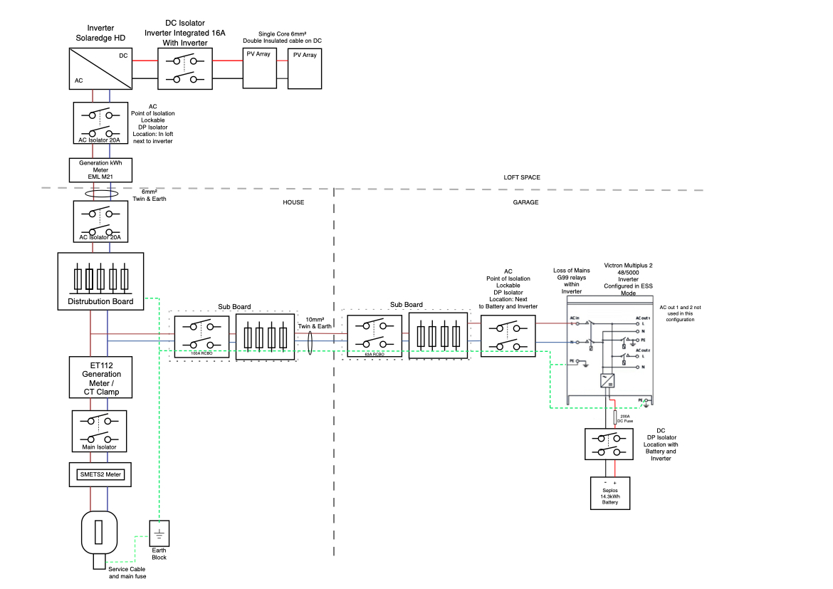
I sent a A1-1 form and single line diagram to SP but received a reply indicating they wanted “a schematic drawing showing the protection systems associated with the automatic disconnecting devices for additional sources of electrical energy including loss of mains protection and trip circuit supervision. G99 protection to be showing at the inverter.”

I have attached the new drawing I am intending to send and would be grateful for any input from those more experienced in this than me.

Also what proof would I need to send them of the Victron’s export being limited to zero or would they want to inspect it?

The are also asking for a location drawing showing boundary lines, xy co-ordinates and substation connection point which I will tackle on return from holiday. I did contact SP for a map request but have not heard back from them yet.

Thanks for your time,

battery-diagram-v3.jpeg


g99
2 |3000

Up to 8 attachments (including images) can be used with a maximum of 190.8 MiB each and 286.6 MiB total.

7 Answers
daza avatar image
daza answered ·

please see thread for examples https://community.victronenergy.com/questions/151406/g99-single-line-diagram.html for the boundary i used a picture from a house plan that we had and highlighted the areas where the battery was and where the boundary is.

2 |3000

Up to 8 attachments (including images) can be used with a maximum of 190.8 MiB each and 286.6 MiB total.

wgoldie avatar image
wgoldie answered ·

I have looked through the thread with interest. I submitted the above drawing and received a reply saying that “G99 protection is still missing from inverters”. Can anyone suggest exactly what I require to add to the drawing for this? I assumed the Victron inverter relay diagram was sufficient but seems not. The only thing I missed out was the control connection from the ET112.

At a loss at the moment to be honest.

Many thanks in advance.

2 |3000

Up to 8 attachments (including images) can be used with a maximum of 190.8 MiB each and 286.6 MiB total.

daza avatar image
daza answered ·

@wgoldie I think it is just you putting the 50amp circuit breaker there take a look at the diagrams everyone has listed it there before the isolator for the inverter you have complicated the diagram with the distro and not said it is this 50amp that feeds this inverter just K.I.S.S (Keep It Stupid Simple)

2 |3000

Up to 8 attachments (including images) can be used with a maximum of 190.8 MiB each and 286.6 MiB total.

wgoldie avatar image
wgoldie answered ·

Thanks, that would have been included in the garage distribution board but I will put it in as a separate item.

2 |3000

Up to 8 attachments (including images) can be used with a maximum of 190.8 MiB each and 286.6 MiB total.

sharpener avatar image
sharpener answered ·

Are they unhappy with the total potential 8kW export? If so can you wire the Solaredge to AC-Out, then its export will be limited to whatever you set on the Multi (and also keep going in a blackout).

I did this and put some text on the G100 part of the form saying the limiting was all internal to the Multi and so the provisions about failed communications links did not apply.

I also sent screenshots of my settings to the DNO with the commissioning form and they seemed to be happy with that. Just as well as with a self-install there is no practical way of "locking" the settings as required by the paperwork.

In addition to the Total Generation Meter you will also need an ET112 to measure the o/p of the Solaredge or it will not show up correctly on the Multi display.

If you are happy doing the mains wiring side you could do that yourself under a Building Notice and get the LA to inspect it, might be easier/cheaper than finding/paying for an electrician to do it.

2 |3000

Up to 8 attachments (including images) can be used with a maximum of 190.8 MiB each and 286.6 MiB total.

wgoldie avatar image
wgoldie answered ·

I’m not sure what they are unhappy about. Every drawing I send comes back with the “G99 not showing at inverter” response. If there is an issue with the existing Solaredge then I may have to look at wiring as you suggest. I was hoping not to mess about with the existing system as it is already approved and working well. I will have to speak to SP on return from holiday.

1 comment
2 |3000

Up to 8 attachments (including images) can be used with a maximum of 190.8 MiB each and 286.6 MiB total.

Craig Chamberlain avatar image Craig Chamberlain commented ·
I was about to say, your best bet is to phone them up and talk to them because in my experience emails just bounce slowly back and forwards for weeks otherwise...

FWIW, I can't see what they are complaining about either.

0 Likes 0 ·
wgoldie avatar image
wgoldie answered ·

I spoke to them today. What they required was a label at the Victron saying “G99 protection within inverter” and at the Solaredge saying “G98 protection within inverter”. Apart from that they were happy with drawing. Now waiting for next stage.

2 |3000

Up to 8 attachments (including images) can be used with a maximum of 190.8 MiB each and 286.6 MiB total.

Related Resources

Additional resources still need to be added for this topic