Good Morning,
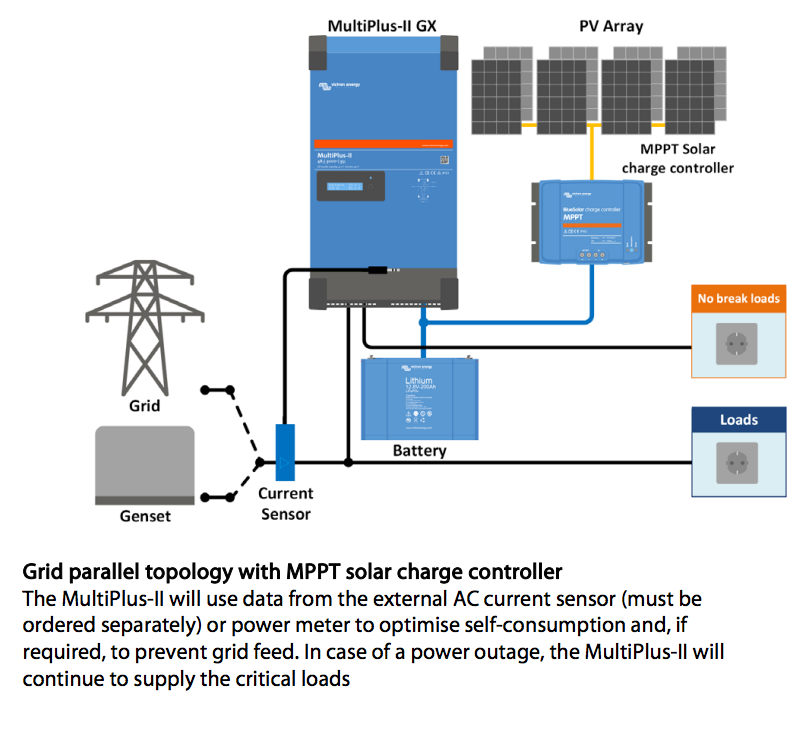
various leaflets and schematics showing the MultiPlus-II GX setup with an ATS for Grid and Gentset and a PV array with MPPT.
Here is the question:
In a few other posts, people mentioning the Aux output (either the Relay on the Multi or the one on the Cerbo GX) to start the generator, after LOM detected "grid is off". The ATS will subsequently switch over to the Genset.
OK, AC-IN L1 will have power from the Genset now.
How does the Multi know, that AC-IN L1 is on the Genset?
I must assume, that the Multi or the Cerbo will switch off the Genset after detecting power at AC-In L1 and end up in a loop until the grid is back online and the ATS switches back to its primary power source.
It must be possible to utilize the Digital inputs for this purpose, i.E. for "feed-in" off (would be a serious problem, if left on, with certain generators), or "charge batteries from the Multi allowed", to utilize the power from the Generator, or "leave AC-Out 2 switched on".
Thanks
Henning
asked
MultiPlus-II GX and Generator ATS
Are these Victron schematics? Because the Official way to do this is to use a Quattro which as 2 inputs, 1 for grid and 1 for Genset. This is the way to do it if you don't already have a MultiPlus.
You can on some grid codes disable feed-in when input active but there is no way to turn LOMs on and off via any input which is normally needed on smaller generators.
Yes, they are official Data sheets,
https://www.victronenergy.com/upload/documents/Datasheet-MultiPlus-II-GX-inverter-charger-EN.pdf
I think, it is a bit misleading.
Henning
I don't know if I would say they are misleading but could be easily misunderstood.
No where do they show an ATS and for the Mobile application you would never use ESS so the inverter would be happy to take both Genset and Grid.
For the Grid Parallel Topology I think they should remove the Genset from this diagram.
@Guy Stewart (Victron Community Manager) Can you give any insight to this? This clearly says Self-consumption yet in most cases you can't transfer in a genset with LOM active. So while this config will technically possible it will result is constant problems if using a small generator. I know it is possible with external LOM equipment but that isn't shown and you will still have the problem with exporting to genset.
Good Morning Guy Steward, I am using the ESS system. My Generator will start incase of Grid failure AND Battery voltage under 48V for 10 sec. I basically need a solution to switch the following functions, in case of Generator usage: ESS OFF, Inverter bypass, feed-in off. Once I can utilize the Digital inputs of the MultiPlus to switch these functions, all is good.
These diagrams are not schematics. They are a representation of what may be possible if you would like to engineer a solution. You can parallel generators to mains ( I used to write PLC software to do that) but you need a use case and you need to be committed to ensure you are prepared to provide the infrastructure to achieve the required outcome.
By purchasing a Multi you don’t have the entire solution. Those simple diagrammatic overall diagrams obviously don’t go into the detail of what is required. That is the beauty of the Quattro because it addresses in the one box so many of the complexities of mixing mains with generator. The beauty is the ability to allow a relatively small generator to handle the inrush currents that would normally demand a large generator. By using the Quattro huge savings can be realised.
To answer one question though if you used the Cerbo to start the generator the Cerbo understand the generator is running. In order to do what you want to be achieved you may need to program a simple PLC to provide inputs to the Cerbo so the complexity of your needs can be realised through a PLC algorithm.
It would be good to know what your requirements are.
Good Morning, I have an PLC-driven Transfer switch and good sized Generator.
That is not the problem. I can also use an external device for LOM detection (a bit costly, but so be it). The actual Problem is switching the ESS, incl. "feed-in" off, to avoid problems with the Generator back-end. This must be possible somehow. I dont have a Cerbo, since the GX device is already built-in.
Okay, so if LOMs is not a problem and you have a PLC is is doable.
Can you send ModbusTCP commands from your PLC?
In the GX remote terminal, menu -> Settings -> Services -> Modbus
If you turn it on then you will be able to control your system via Modbus, doesn't have to be a cerbo, internal GX is basically the same thing.
https://www.victronenergy.com/live/ccgx:modbustcp_faq
When switching to Generator:
ESS Mode - Register 2902 set to 3 (This will disable ESS)
Feed excess DC-coupled PV into grid - Register 2707 set to 0 (Will stop DC feed-in)
You can then set L1 Setpoint - Register 37 to whatever power you want from the genset.
Eg. If you set it to 4000 then the inverter would only draw 4000W from the genset, if the loads as less than 4kw it use that extra power to charge batteries, if loads are higher it will add power from batteries.
When switching to Grid.
ESS Mode - Register 2902 set to your normal mode
Feed excess DC-coupled PV into grid - Register 2707 set to 1 if you want to export excess PV.
L1 Setpoint will be controlled by Victron ESS control loop.
Full list of modbus registers can be found here.
https://www.victronenergy.com/support-and-downloads/technical-information
Hi Shaneyake, brilliant, I will implement this solution over the weekend.
Thanks a lot.
Henning