question

John Wilson avatar image
John Wilson asked

BMV-712 SOC to zero in 23 min of 170 min LOAD Test

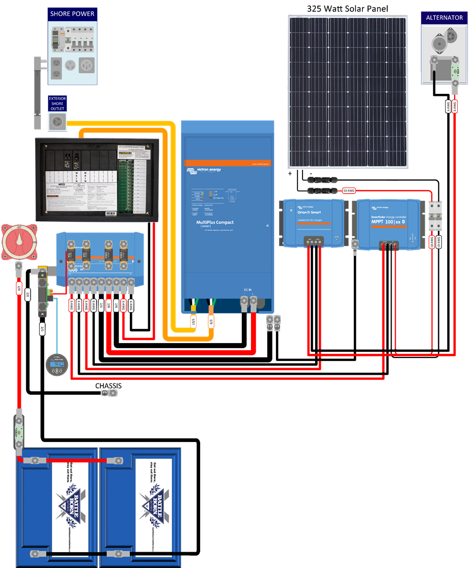
I have a 300 Ah system. Battleborn batteries, Victron Multiplus Compact 12/2000/80 120V, using an EXPLORISTlife wiring diagram. I have run a full load test by running a 1200 hot air gun continuously until the Multiplus inverter shuts down (this is after full Shore Power charge).

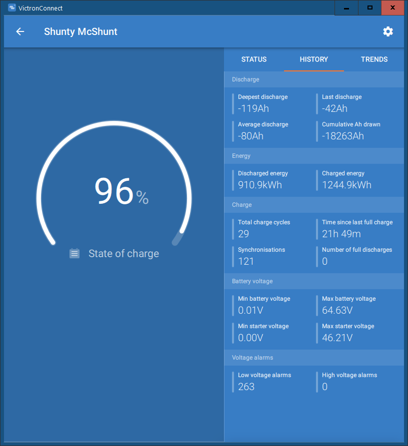
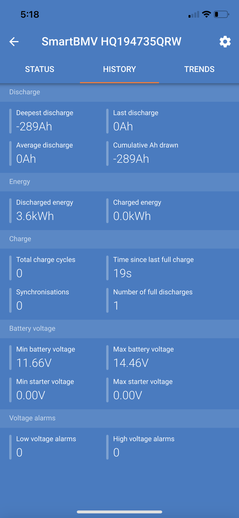
The good news is I am getting what I should expect from the battery bank. 170 minutes at 1245 Watts = 293 Amp Hours.

The bad news is that the BMV-712 SOC went to zero 23 minutes into this test.

I ran this test at Battleborn's recommendation because I was seeing this odd behavior from the BMV.

The idea of the test was to determine which was correct? The BMV or the actual output of the system. So the test confirms the system is working and the BMV is way off. I am using Battleborn recommended BMV settings

Battery capacity 300aH

Charged voltage 14.2v

Discharge floor 0%

Tail current 4%

Charged detection time 3m

Peukert Exponent 1.05

Charge efficiency factor 99%

Current Threshold 0.10A

Time to go Averaging period 3M

Battleborn suggested replacing the SHUNT PC Board. I did, and I am still getting the same behavior.

Any ideas? Could the BMV-712 unit be bad? SOC is a calculation. Maybe the Calculator is not functioning correctly. I have read many posts on SOC errors and accuracy. I know the BMV reported value is not perfect, but this is so far off it is useless.

Help? Ideas to try for further diagnosing would be appreciated.

Thanks!

John


Wiring diagram below (third battery not shown).

1639152813231.png


1639153008044.jpeg


1639153186199.jpeg

BMV Battery Monitor
1639152813231.png (524.3 KiB)
1639153008044.jpeg (452.7 KiB)
1639153186199.jpeg (369.9 KiB)
2 |3000

Up to 8 attachments (including images) can be used with a maximum of 190.8 MiB each and 286.6 MiB total.

5 Answers
John Wilson avatar image
John Wilson answered ·

Here is the data from the Load Test

1639154981667.jpeg


1639154981667.jpeg (115.1 KiB)
2 |3000

Up to 8 attachments (including images) can be used with a maximum of 190.8 MiB each and 286.6 MiB total.

snoobler avatar image
snoobler answered ·

Does the BMV report the expected current during the test?


If not, is it correctly configured for a 500A/50mV shunt under Misc?


Are you using the aux input for temperature? If so, is the temperature reading accurate, and are you using the temperature capacity coefficient?

1 comment
2 |3000

Up to 8 attachments (including images) can be used with a maximum of 190.8 MiB each and 286.6 MiB total.

John Wilson avatar image John Wilson commented ·
Hi, thanks for responding,


Yes I checked the current with an Ammeter during the test multiple times and the reported current from the BVM agreed with the Ammeter.

Yes the BMV has the 500A/50mV selected under Misc.

No I am not using the auxiliary temperature sensor. None is selected in the drop down menu.

John


0 Likes 0 ·
snoobler avatar image
snoobler answered ·

I can only conclude the BMV is defective. If it's measuring the correct current, it should correctly count the current and compute vs. programmed capacity. . Since you're not using temperature based capacity compensation (not a thing with LFP), I can't see what else is effecting it as you have Peukert set to 1.05.

Does the History page seem consistent with the SoC calculation?


1639172123671.png


1639172123671.png (84.1 KiB)
1 comment
2 |3000

Up to 8 attachments (including images) can be used with a maximum of 190.8 MiB each and 286.6 MiB total.

John Wilson avatar image John Wilson commented ·

Hi, yes it did track. I had zeroed out the history before this test and it captured correctly the consumed Ah. See photo:


1639236981893.png

0 Likes 0 ·
1639236981893.png (234.0 KiB)
Trevor Bird avatar image
Trevor Bird answered ·

Hello, we recently had a problem with a BMV712 reading incorrect current through the shunt. A current was being read but much lower than the actual current. It turned out to be the data cable (6 core RJ12 I think) between the BMV712 readout and the shunt. A couple of the pairs were open circuit.


I know you are reading the correct current through the shunt and the readout should work out the SOC from that but perhaps it may be worth simply replacing that cable in the first instance and see if it makes a difference. We replaced the BMV712 with a new one before we opted for the simplest solution first.

Anyway, it may be worth a try.

2 comments
2 |3000

Up to 8 attachments (including images) can be used with a maximum of 190.8 MiB each and 286.6 MiB total.

John Wilson avatar image John Wilson commented ·
Thanks for the good suggestion. I'll give that a try and report back!
0 Likes 0 ·
kevgermany avatar image kevgermany ♦♦ John Wilson commented ·
Guessing you did, but worth checking the BMV was showing 100% SOC at the start of the test.

It would be interesting to know if it shows a SOC in line with the charge rate when you recharge.


0 Likes 0 ·
John Wilson avatar image
John Wilson answered ·

An update. The system seems to be working correctly now but I am not sure why? I did a Zero Current calibration (ie remove the load side of the Shunt and calibrate through the Victron BMV app). And I disabled the Relay function (that was enabled for some reason....probably something I did by accident). Then I ran another test and the system is behaving as expected. So what did I do? Maybe the Shunt PCA was the culprit? Could the Relay function be doing anything? Feeling dumb but happy the system is working.

2 |3000

Up to 8 attachments (including images) can be used with a maximum of 190.8 MiB each and 286.6 MiB total.