Good day,
I have installed the Victron BVM 712 in a Battery box, and it correctly displayed both battery voltages.
I have since rebuilt the battery box with a LiFePo4 battery and have also installed a Orion DC-DC charger, 2 x Busbars (+ and -), as well as a 60A Trip switch inline with the Main battery Positive cables.
Now the AUX battery is displaying 0.3v.
This is the strange part: The 60A trip switch is installed on a plastic case, splitting the Positive cable from the House Battery (LiFePo4) between the battery and the Postiive Bus bar.
When I touch any one of the + points on the inline Trip switch, the voltage jumps from 0.3 v to 19v, depending on how hard I press, and touch on any metal object.
I have checked my wiring and nothing is earthed as all of my Battery Box is Isolated. No Earth points anywhere. I run separate cables for earth. Even die DC-DC charger is the Isolated type.
I did use the Positive (from the AUX battery) at the + INPUT port of the DC-DC charger as a feed into the 1st ferrule port next to the 'network' port.
What am I missing here?
Thanking you in advance!
asked
BVM 712 Aux Battery Voltage error - Displaying 0.3v

My wiring diagram if this will help
I'm surprised you're getting any reading. According to the wiring diagram, there's no BMV.
Seriously I think you answered your own question. Faulty 60A trip. That's probably the best place to start. Do you have power at the busbars with all the charging switched off?
Hi Kevgermany
The 60A trip is working in that when open / switched off, zero power (volts, amps lights etc) to the Monitor.
When closed all is working as expected, bar the AUX battery voltage of 0.3v
(I have connected the BMV monitor via the RJ12 UTP cable, and can view via my cell)
Thank you for your input
The shunt has two positive wires, both thin, both go to the green connectors . I think both are fused. The left one nearest battery side of the shunt goes to the battery the shunt is connected to. The other can go to starter/aux battery or mid point of of a 24V system.
You should never see 19V in your system.
You only have one battery in your diagram. But you mention aux battery. I guess the diagram shows what you call aux battery. Where is the left red wire connected? Busbar, battery side of switch, busbar side of switch, elsewhere?
My guess is there's a loose connection in the area of the switch you're pressing. Or a faulty switch.
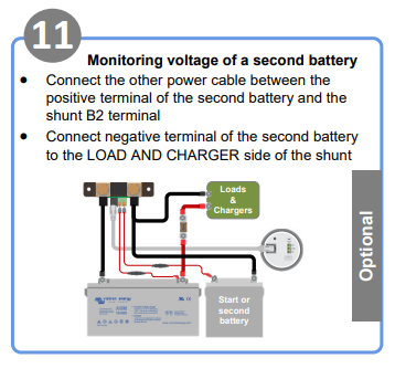
Are you sure your connection to the Aux battery is correct? In the quick start guide for the BMV712 there is a wiring diagram showing the negative of the Aux battery connected to the load side of the shunt. If you have it connected to the battery side of the shunt the BMV aux voltage reading may also include the voltage drop across the shunt. Unlikely to be 0.3V but still significant perhaps.
Good day, Thank you for the input.
I agree my diagram is not that explicit. Allow me to elaborate:
I have used the 2 thin red wires connected to the green terminals of the Shunt in the following manner.
1) The RIGHT red thin wire as per the diagram above (11), is connected to the + of the Input terminal of the DC-DC charger. This is turn is connected to the + of the 'Aux' Battery / Alternator with a 16mm cable. (Marked with a red BH plug called "FROM Alternator" in my diagram). Since the starter battery / Alternator is in the engine bay of the vehicle and my electrical box in the back of the vehicle, this is the only connection I have to the starter battery to connect the 1st red wire to.
2) The LEFT red thin wire is connected to the + cable from the House battery, and was later moved to the + Bus Bar. (Marked with a GREY BH plug called "to Battery" in my diagram). I did this in an attempt to isolate the 60A trip switch.
Something else I have noticed, which leads me to believe that my body's static electricity has an effect on the reading of the Aux Volts reading. Every time I touch the thin red wire terminal with my finger the voltage improves from 0.03v to a higher value - but only for a second or two.
When I touch the terminal again and touch anything else, even a rubber door seal, the voltage improves to an even higher V reading. The harder I press, the higher the V reading (On one such an event I did see 18.x v) - but only for 1 or 2 seconds, then it drops back to 0.03v
The Shunt negative terminals are connected correctly in that the - Bus Bar is connected to the Load side of the Shunt. The remaining terminal is connected to the House Battery via a 16mm Cable. (Marked with a GREY BH plug called "to Battery" in my diagram)
I will disassemble the Battery Box this weekend and attempt to find anything that I may have missed in the past.
(I am also fitting the MPPT charger as per the diagram - awaiting delivery)
Thank you for the input!