question

maximoney1 avatar image
maximoney1 asked

Can you operate the remote on/off terminals on a multiplus 24/3000/70-16 and a 150/45TR SCC using generic BMS relays?

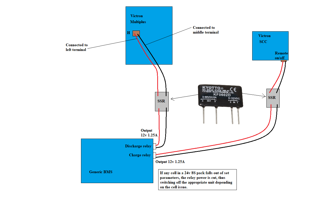
I have a charge relay and separate discharge relay on a generic BMS, to protect individual cells on a 24v 8S lifepo4 pack. These are always on, outputting 12v and 1.25A whilst the cells remain within the parameters. Is it possible to use the discharge relay to connect to the H terminal(left & middle terminals)on the multiplus and the charge relay to the SCC? I had hoped that the use of a SSR would provide the isolation and simply act like a switch. The 'charging' function of the multiplus will not be in use.

Please see simple diagram below for an idea of what i'm proposing.

Opinions welcomebms-connection-layout.png

Multiplus-II
2 |3000

Up to 8 attachments (including images) can be used with a maximum of 190.8 MiB each and 286.6 MiB total.

2 Answers
bathnm avatar image
bathnm answered ·

Yes this could work. However you also need charge disconnect on the MultiPlus.

You could use the 2-Wire Assistant on the MultiPlus, by connecting the SSR output of the Charge Disconnect to Aux1 and an SSR connected to the Load Disconnect to Aux2. Then configure the 2-Wire assistant that with Aux1 is closed charge is possible and while Aux2 os closed load is possible. When either relay opens the relevant capability is disabled.

See this link on the 2-wire assistant

2 |3000

Up to 8 attachments (including images) can be used with a maximum of 190.8 MiB each and 286.6 MiB total.

maximoney1 avatar image
maximoney1 answered ·

Thanks bathnm, i would only very rarely be using the 'charging function' on the multiplus and i was simply going to SSR the incoming grid power(which might only be connected once per year) to disconnect the live/hot wire. I could either parallel on the BMS charge relay or else, potentially use the programmable relay output on the SCC to cut the control voltage to the grid supply SSR. I just didnt show this aspect as i might never use the charge function on the multiplus at all and didnt want to complicate things.

Obviously the SSR would be very different from the one shown in the diagram, since it would be 'breaking' AC.


1 comment
2 |3000

Up to 8 attachments (including images) can be used with a maximum of 190.8 MiB each and 286.6 MiB total.

bathnm avatar image bathnm commented ·

If you cut the AC input, which would work it also means that pass through in Charge Disconnect would not work. If you don't want to use the charge at all, then do not wire anything to the Aux2, it will always be open and therefore not charge.

That said if you never want to charge and do not want the hassle of installing and configuring an assistant then using the load disconnect to break the shorting of the remote H terminal (left and centre) would also work. Just need to ensure that it is never able to switch to charge mode when mains is connected, incase a charge disconnect event occurs and it doesn't get disconnected.

0 Likes 0 ·

Related Resources

Additional resources still need to be added for this topic