question

Rob Duthie avatar image
Rob Duthie asked

AC current sensor not working when plugged into a Mulitplus 2 unit?

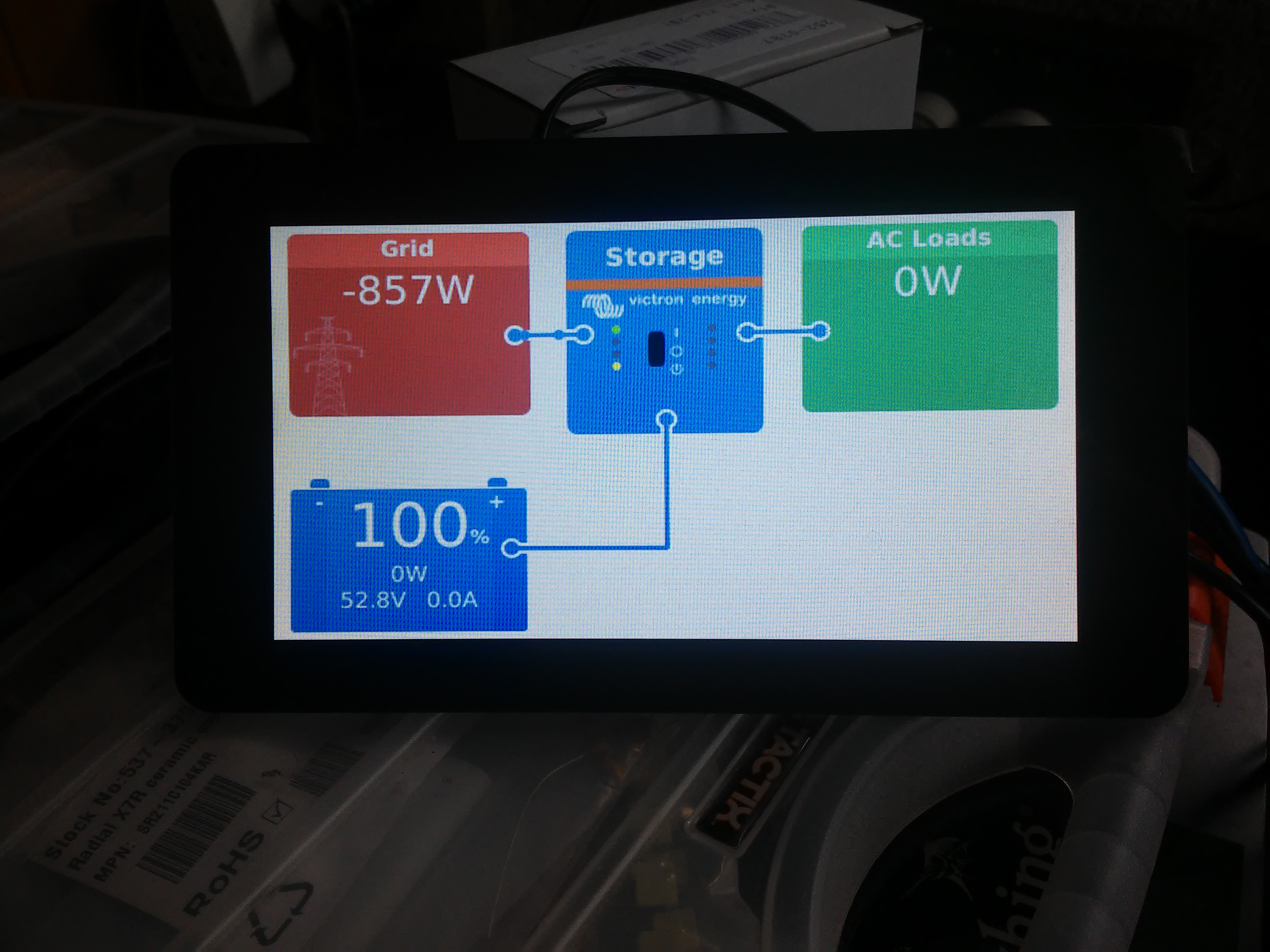
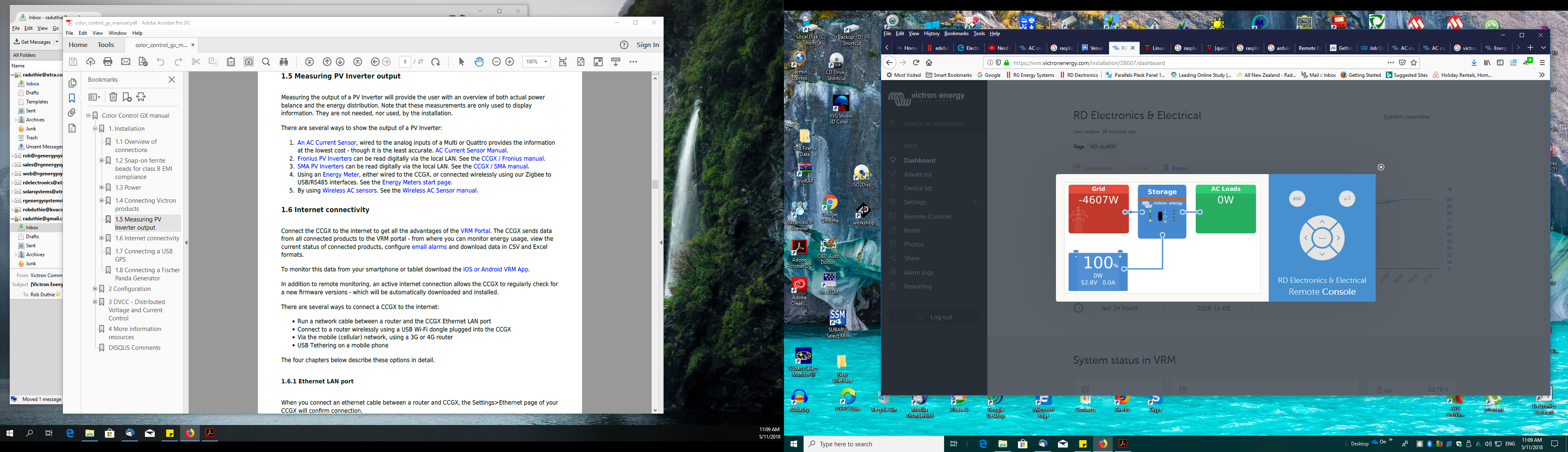
AC current senor does not read current when plugged into the Mulitplus 2 unit? I fact when it is plugged in it cuts the reading for all AC current on the AC Input?

I have noticed a few bugs in the Mulitplus 2 software in operation when in ESS mode.

It does not work as it should i will compile a list of error i have found.

This unit has 2x internal current sensors correct? One on the AC input and output of the inverter

as per manual in appendix?

so it can measure current flow in either direction i believe.

So why can't it measure and display it correctly then?

It should be able to measure current flowing in any direction with a grid tied inverter connected to the AC2 out.

Multiplus-II
2 |3000

Up to 8 attachments (including images) can be used with a maximum of 190.8 MiB each and 286.6 MiB total.

5 Answers
Guy Stewart (Victron Community Manager) avatar image
Guy Stewart (Victron Community Manager) answered ·

Have you enabled the AC current sensor in VEConfigure?

2 |3000

Up to 8 attachments (including images) can be used with a maximum of 190.8 MiB each and 286.6 MiB total.

mvader (Victron Energy) avatar image
mvader (Victron Energy) answered ·

When the external one is inserted, the internal one doesn’t work anymore.


The feature of this specific accessory is to replace the internal one, not to add one.

2 |3000

Up to 8 attachments (including images) can be used with a maximum of 190.8 MiB each and 286.6 MiB total.

Rob Duthie avatar image
Rob Duthie answered ·

Hi

Thanks for that, so the energy meters can only plug into and use the RS485 to USB converter from the ET112 unit?

1 comment
2 |3000

Up to 8 attachments (including images) can be used with a maximum of 190.8 MiB each and 286.6 MiB total.

mvader (Victron Energy) avatar image mvader (Victron Energy) ♦♦ commented ·

See the manuals. (or perhaps someone else here from the community can help)

0 Likes 0 ·
Rob Duthie avatar image
Rob Duthie answered ·

Hi

Yes so i have found out, when playing around with the settings as there no mention in the manuals anywhere to advise of this. All it is a extension so you can measure more current and have access to the switchboard cable so you can measure the main grid current etc.

Just a note to make everybody happy with how the ESS system works with other grid tie inverters, (not Froius types) would be to enable a icon(other gridtie PV inverter) on the CCGX displaying the PV inverter box, so when there is excess current being sent to the grid it shows up on the screen as negative kW with flow lines to the Mulitplus 2 which i have under test here in New Zealand, This would save a lot of questions about this the ESS not showing this, which is just a software update, and would make this a very cool feature for the Mulitplus units, and to all the other Grid tie PV inverters out there?

As i am trying to sell this idea to people who don't have a Froius grid tie inverter.

if you like i could draw up a screen profile and write a full description etc.


Note: this is one feature it needs to make it a true ESS system, as when you read the brochures etc it sound i can do this for all inverters only. The catch is you need a Froius type).

Please advise

1 comment
2 |3000

Up to 8 attachments (including images) can be used with a maximum of 190.8 MiB each and 286.6 MiB total.

mvader (Victron Energy) avatar image mvader (Victron Energy) ♦♦ commented ·

Hi, you don't need a Fronius for visualisation on the CCGX. See CCGX manual, section about measuring PV Inverter Output. (I hope I got your question/remark right).

0 Likes 0 ·
Rob Duthie avatar image
Rob Duthie answered ·

Hi

Yes sort of, looks like that is what you have designed into from the start to use.

what i proposed is a simpler idea to sell and use the internal current sensor to do both, as it see current flowing in two direction import and export, soon as it see's a export of energy it displays it on the CCGX under the PV inverter box icon. To me this is more logical and makes the Mulitplus 2 a more simple unit to install and keeping it simple for installing etc.

I have a fully ported rasbpi2 3B+ with a 7 inch touch screen running except for the WiFi, which is my next step o fix.

I am willing to be test bed for the ESS system for the Mulitplus and to debug etc.

I have 3x grid ties system running 2 at 2kw each and a 600watt unit, the inverters are Mastervolt

and Enasolar made in New Zealand, with a small 40Ah 48 battery pack to load testing etc.


1 comment
2 |3000

Up to 8 attachments (including images) can be used with a maximum of 190.8 MiB each and 286.6 MiB total.

mvader (Victron Energy) avatar image mvader (Victron Energy) ♦♦ commented ·

yes, that could be a nice solution; but the shown numbers will most probably be wrong tough; The system will never know how much power is going from the PV Inverter to the loads. The only thing it sees is the difference.


I'm still convinced that its better to mandate making sure the PV Inverter is being measured. One way (Fronius, SMA, & other ModbusTCP compliant inverters) or another (add an energy meter).


And not add code to make a visualisation that will be wrong.


0 Likes 0 ·

Related Resources

Additional resources still need to be added for this topic