question

jerem avatar image
jerem asked

PV and Alternator loads with miniBMS

Hello everyone, I am inspiring myself from this very complete and documented project example provided by Victron: https://community.victronenergy.com/content/kbentry/15035/victron-vw-van-electrics-install-schematic-drawing.html

But the fact is that it is too complete for me. I do want to have the following features:

- Load through Van alternator (I have Euro 5)

- Load through solar panels

I don't want the grid part of it. Many different reasons: too expensive, convert 12V DC to 220V AC result in energy loss and in some countries, 220V AC can be dangerous (electrocuted) and needs the approval of a certified electrician.

So I am taking parts of the two sub-schematics: solar and alternator but I have some questions.


- Do I need the Lynx Distributor? If I have my own fuse box it should be fine I guess

- The negative of car battery is not connected to rest of electronic circuit but it should be right? In the example it is only connected to the negative of Buck-Boost part.

- Do I need the full BMV 712 system? With Solar Panels, I understand that to load with the engine's alternator, we need a management to protect the Lithium battery. But isn't the Buck-Boost already here for that?

- About the Buck-Boost in the example, I understand that the two green and purple cables are connected together. Why? I would gladly have more explanations about the connection between Buck-Boost -> BP 100 -> BMV Smart -> VE.Bus BMS. I have the feeling there are some redundancy here. Am I wrong?


My idea about the connection would be following:

- Solar Panels -> MPPT -> BP100 -> Positive of Lithium battery

- Engine alternator/battery -> Buck Booster -> same BP100 as before -> positive of Lithium battery

- VE.Bus BMS managing both BP10 and Buck Booster

- Lithium battery -> 12 V loads.

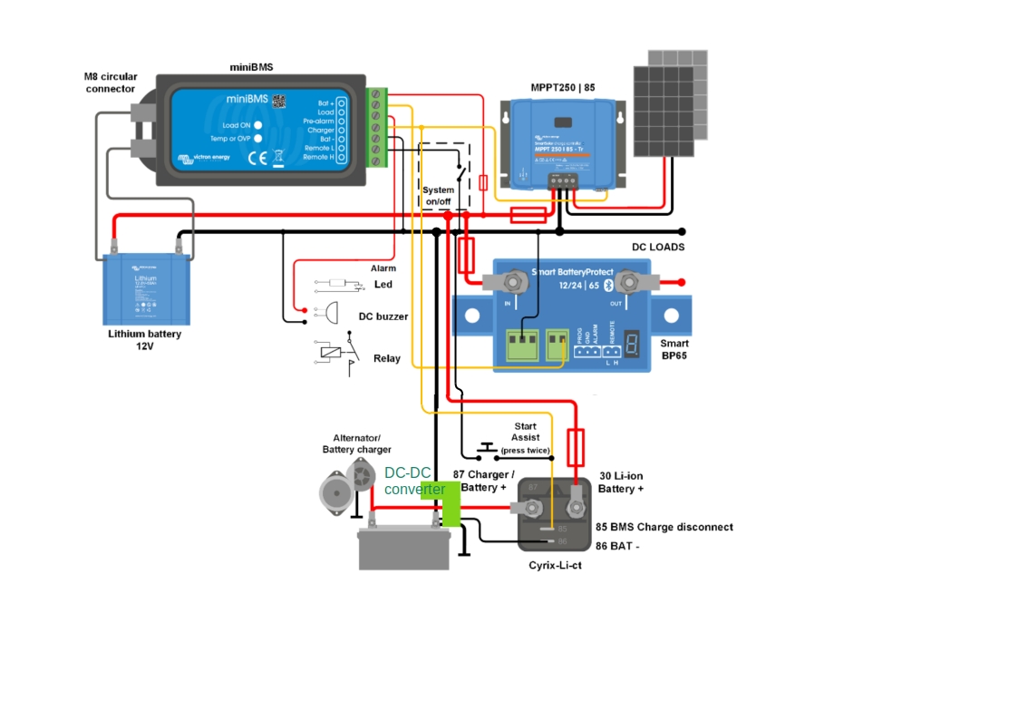
Here is my beautiful plan, I just showed the positive (in red) as all negatives are connected., VE.Bus BMS gets the info from Lithium battery (black line) and Buck Booster (purple line) and manages both BP100 (green lines)


Thank you for your help and advice!

Jerem

campervan
2 |3000

Up to 8 attachments (including images) can be used with a maximum of 190.8 MiB each and 286.6 MiB total.

2 Answers
jerem avatar image
jerem answered ·

Hello everyone, sadly nobody could reply so I did pursue my research with Victron products to get an electrical circuit corresponding to my needs.

I must say Victron provide a lot of examples, which is very good but they are almost all different and very complex. I am searching since many days for a simple and light example using Alternator and Solar Panels as Load input and start to lose faith, but anyway! I hope I found the good schematic. I mixed the both examples provided by in miniBMS datasheet

Here we go:

There are two tricks:

- First: add a isolated DC-DC converter between Cyrix-li-Ct and engine's electric circuit to "emulate" a constant 12V 30A DC and thus get rid of smart alternator/engine problems on Euro5 cars.

- Second: it is to put two devices on miniBMS "Load" output and I don't know if it is possible. Here Victron's documentation lacks of electronic info.

I know that miniBMS is "high" if everything fine, with 10 mA (absorbing or providing?)
Cyrix will be activated if its input "85" is set to high, same for MPPT.

So my first question is: is it possible to plug two "Loader's input from miniBMS" on "Load" output of miniBMS?


Then as I pursued my research, I found this schematic which is also very interesting but still some questions remains:

https://www.victronenergy.com/upload/documents/VE-direct-drawing-with-Phoenix-charger-12-50-1-inverter-375W-Li-Batt-mini-BMS-MPPT-100-30-Orion-Tr-smart.pdf

I don't use the Phoenix part, still no 230V in my Van needed.

I find it very interesting because Alternator load and PV load are both controlled by miniBMS through one Cyrix Li. But then there is this PV Breaker Isolator and I can't find any documentation about this device, except schematic. What is it used for?


Thank you for your help
Jerem


2 |3000

Up to 8 attachments (including images) can be used with a maximum of 190.8 MiB each and 286.6 MiB total.

dwkennedy avatar image
dwkennedy answered ·

I would think you could attach any number of loads, so long as you don't draw more than 1A total from the load output of the miniBMS. That would only be a problem if you needed to run big relays to switch the load. Other devices may only use the voltage as a signal and not draw a significant amount (milliamps)

1 comment
2 |3000

Up to 8 attachments (including images) can be used with a maximum of 190.8 MiB each and 286.6 MiB total.

jerem avatar image jerem commented ·

Hello dwkennedy, I thought it also, I hope it will try it and hope it work well.
On my PV module configuration I will need a MPPT 100/30 so I will have to cut MPPT off with a BP65 anyway.

Thank you for your help!

0 Likes 0 ·

Related Resources

Additional resources still need to be added for this topic