question

ronr avatar image
ronr asked

MPPT & BMV current discrepancy?


I just installed the Victron 100/30 controller.

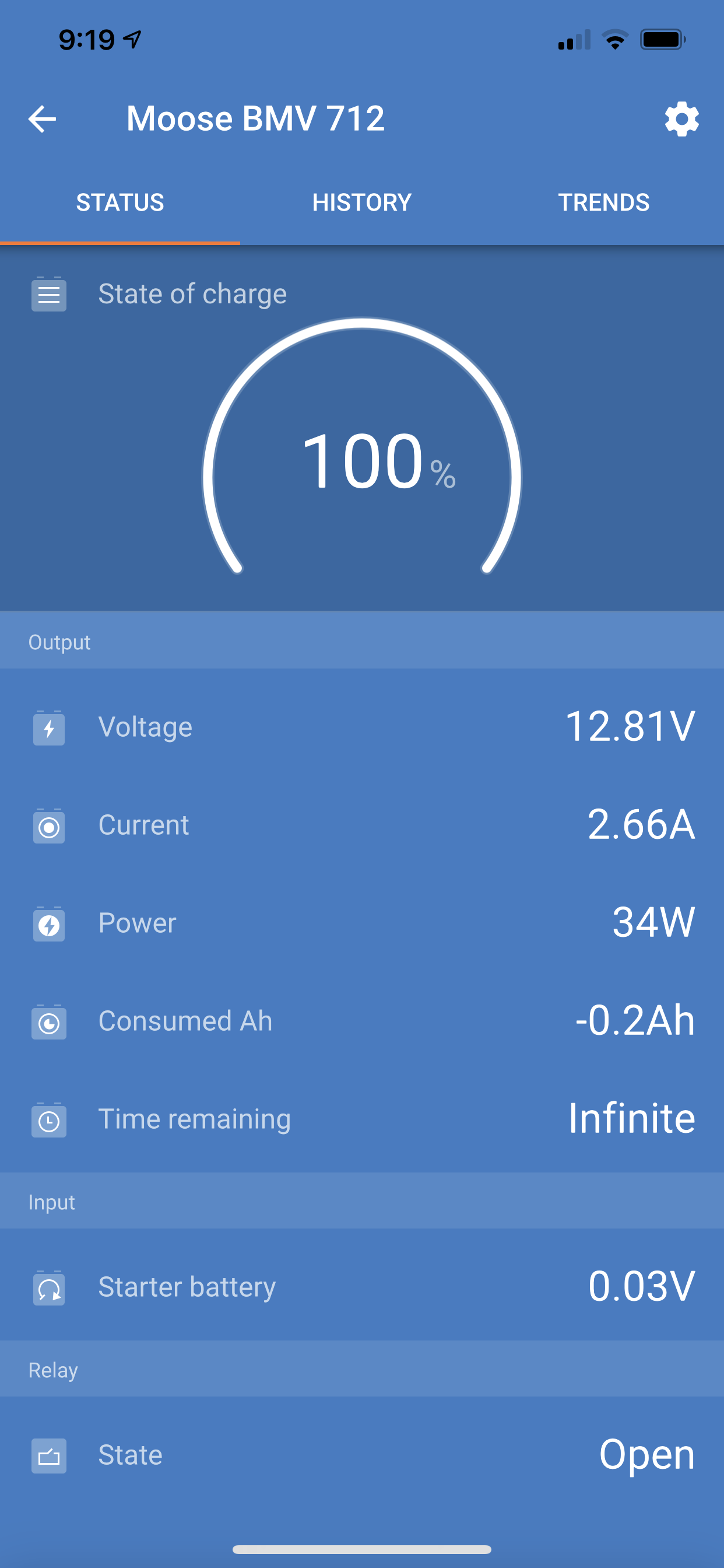
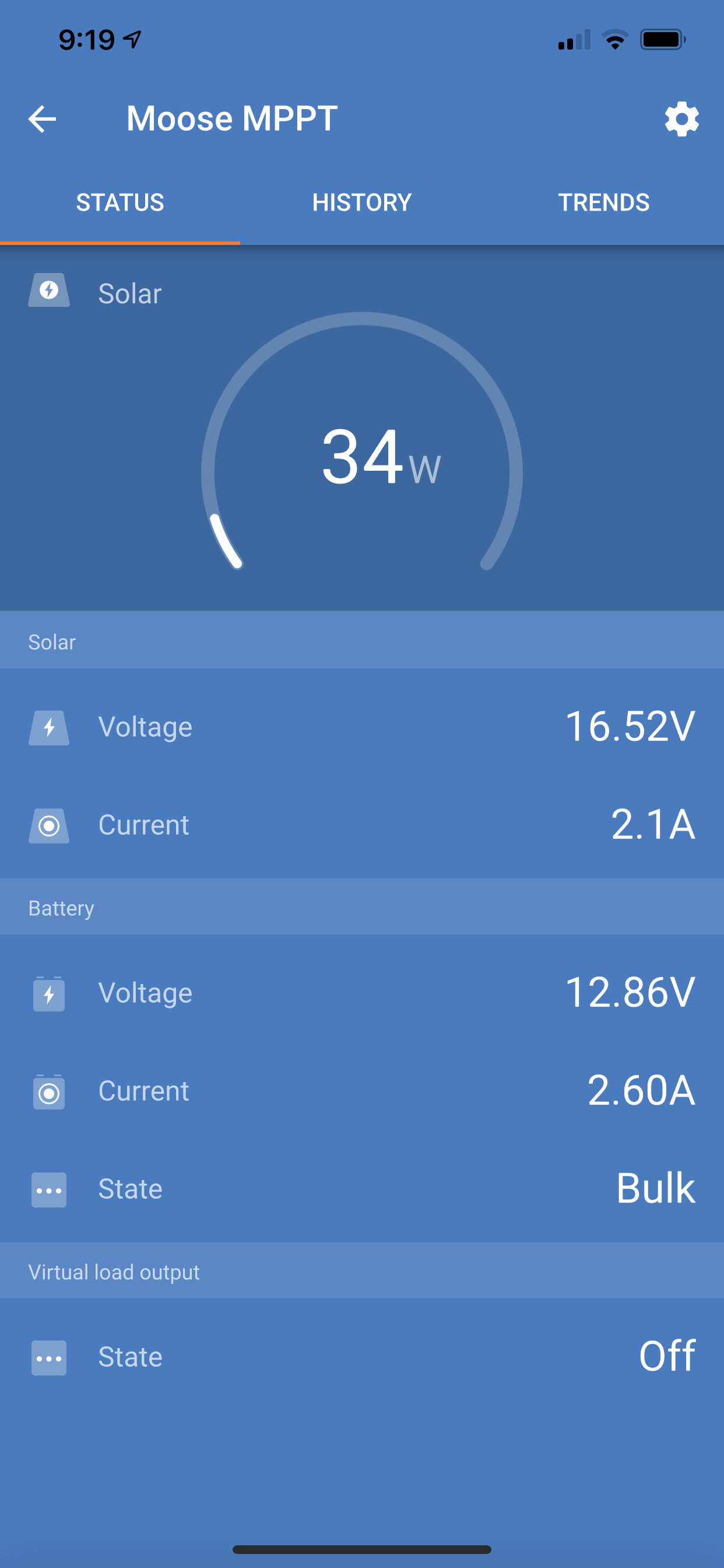
Prior to the installation of the new MPPT, I had been monitoring my two Life line 220 AH 6 volt batteries in series with a Victron BMV 712. Voltage and amps seemed to be at appropriate levels for my 160 Zamp panel and Zamp PWM controller with a top current under ideal conditions with no load on bulk at about 7 amps.

So that was the previous set up until I installed the MPPT. The only difference was the new MPPT.

I’ve setup the new MPPT according to specs directly from Lifeline.

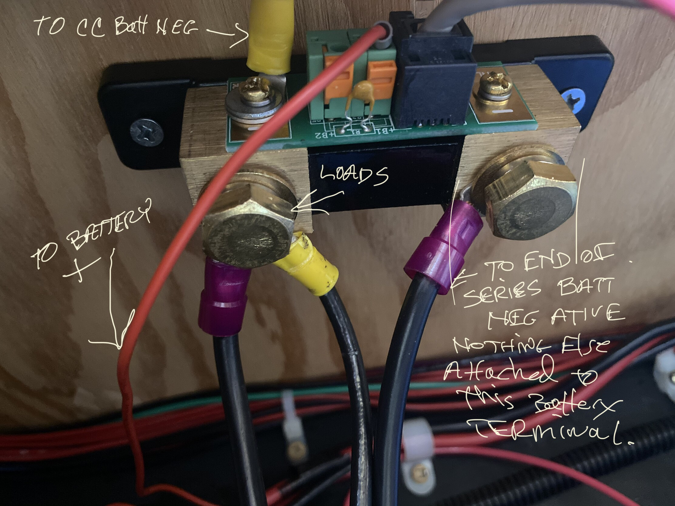
I have checked and believe I have both controller and monitor wired properly. All negatives are going through the shunt of the BMV and the only thing connected to the negative battery terminal is the shunt.

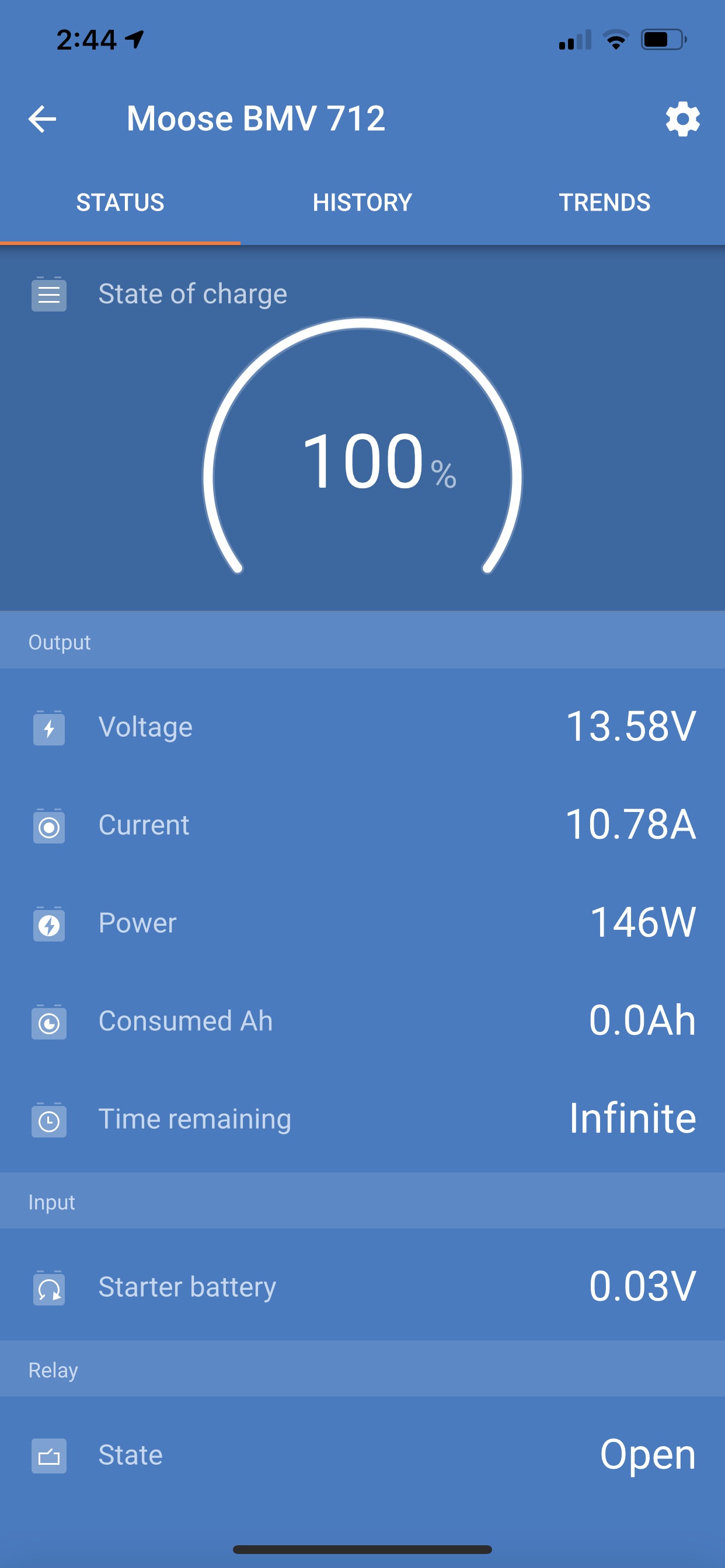
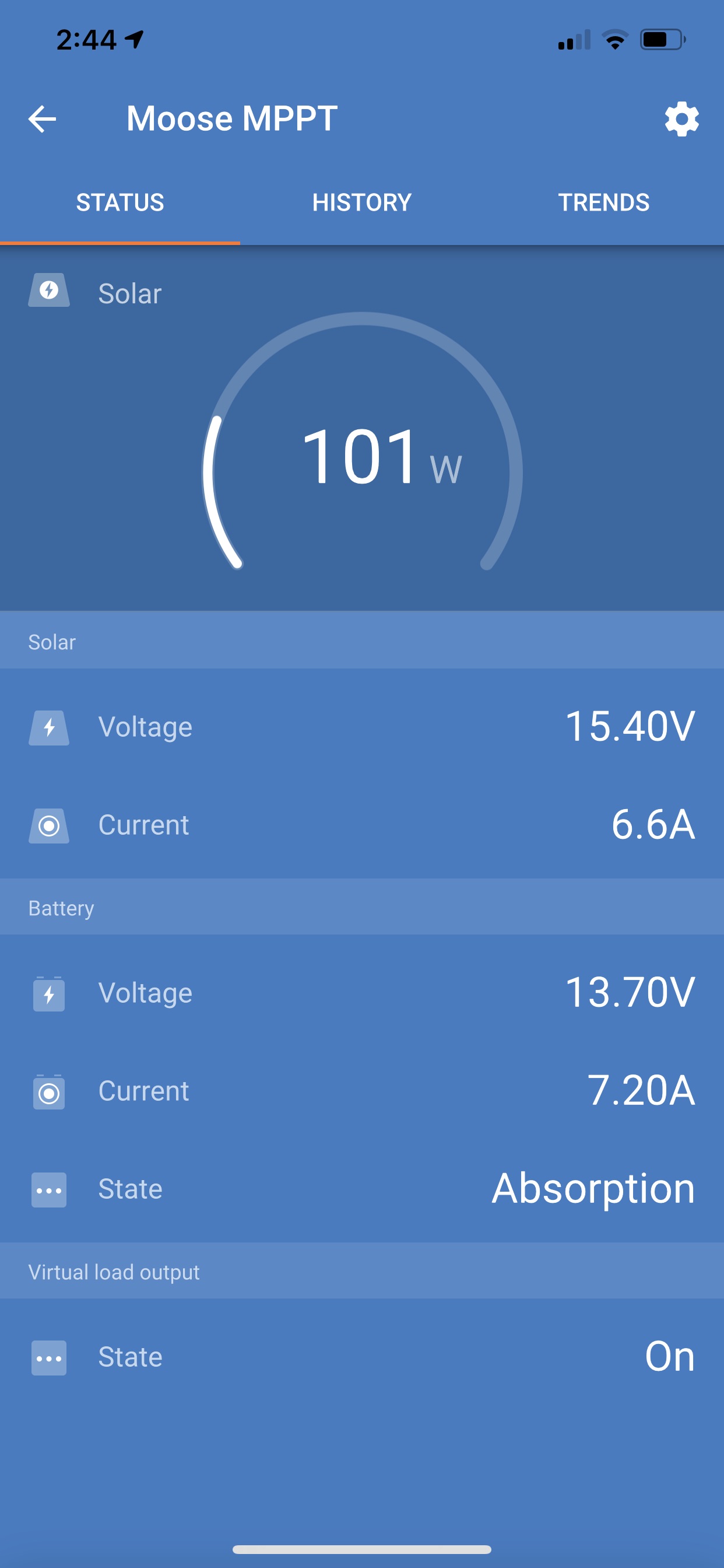
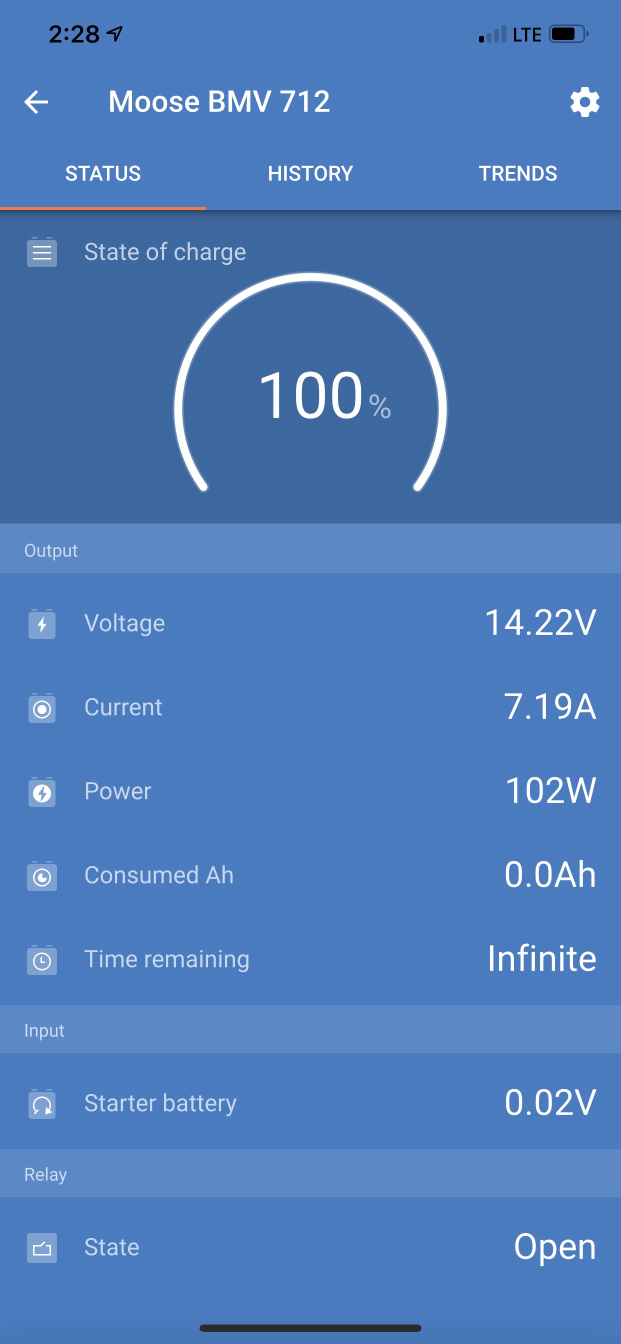
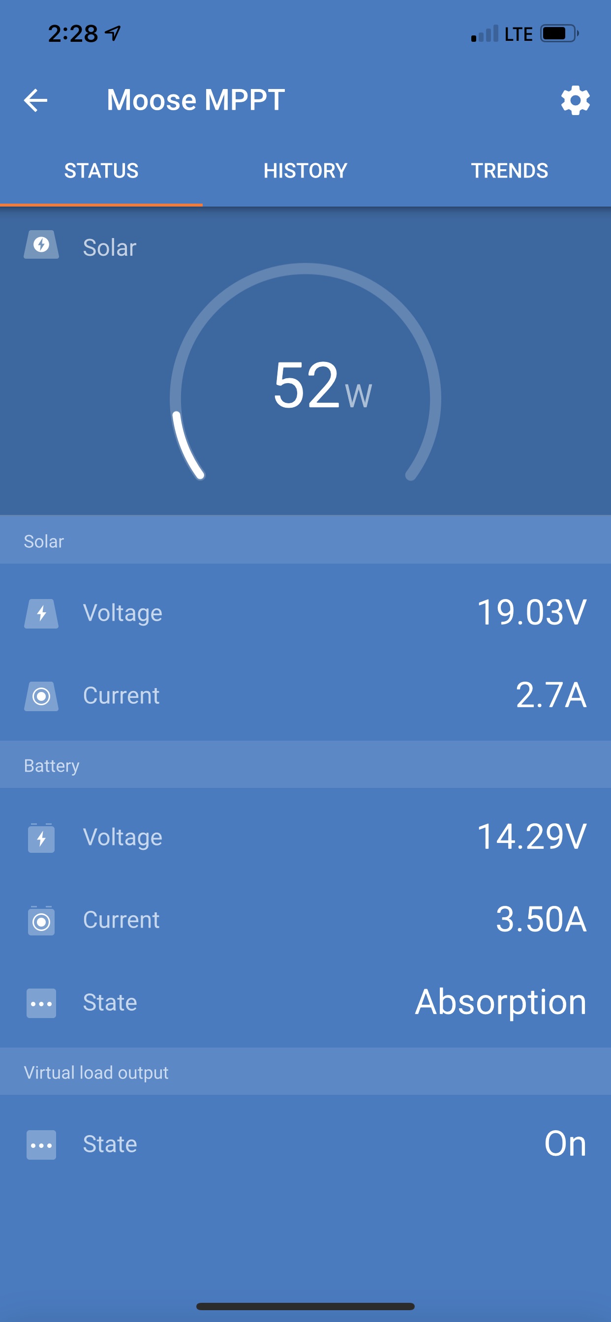
I’m concerned that the amps shown for the batteries are significantly different between the BMV and MPPT. For these screen shots I turned off my master switch so the only loads I can think of are from the BMV and Mppt which are powered directly from the battery. Also there are no other charging sources other than the solar panel. The following screenshots show:

BVM current: 10.78 A
MTTP current (battery): 7.2 A

Again my master switch is off, so there is no load and there is no other charging source other than solar. Before the new controller, I never got close to 10.78 current as now shown on the BMV.

Does it make sense the BMV current is 3.5 amps more than the MPPT battery current?


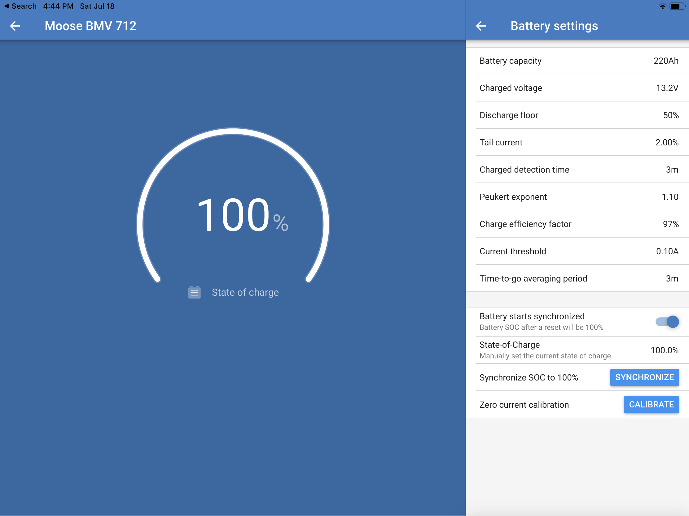
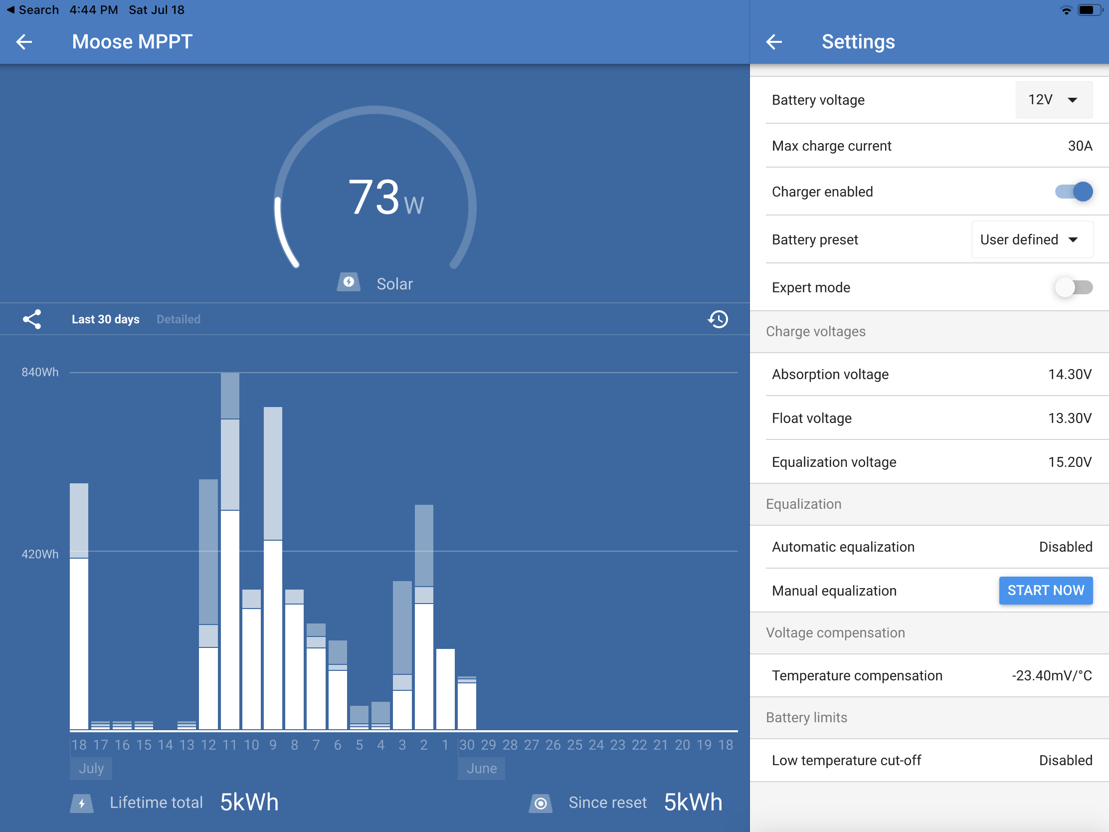
And here are the settings for each device


BMV Battery MonitorMPPT SmartSolar
2 |3000

Up to 8 attachments (including images) can be used with a maximum of 190.8 MiB each and 286.6 MiB total.

3 Answers
wkirby avatar image
wkirby answered ·

In the photograph that you attached, it shows that you have removed at least one of the screws that hold the PCB on to the shunt. You have also connected a wire from the Charge controller there.
This may seem innocuous, but this can add a small amount of resistance to the overall shunt resistance which will definitely throw the current reading off.

The resistance of the shunt is 0.0001Ω. So, even if you add 0,0001Ω the error will double.
The PCB terminals are a point on shunt where the Voltage measurements are made. These Voltages are tiny, 0.0005V if 5A is flowing through the shunt.

So, in your case, the charge controller is forcing current through that small screw which will cause a higher Voltage on the PCB terminal than the actual shunt terminal. The little screw also has resistance and is acting as a shunt its self. The PCB terminals are supposed to measure the Voltage drop over the shunt which relates to the current going through it.

To fix this, you need to remove any wires connected via those little PCB screws and return those screws how they were from the factory, Then connect the charge controller wire to the actual shunt terminal where the other wires are.
You may need to do another zero current calibration.

I can appreciate the temptation to use those screws for attaching smaller lugs or wires, but this causes the problems that you are having for the reasons that I have explained.


3 comments
2 |3000

Up to 8 attachments (including images) can be used with a maximum of 190.8 MiB each and 286.6 MiB total.

ronr avatar image ronr commented ·

Wow!!! That fixed it. I can’t thank you enough. I’ve worked hours and hours on trying to figure this out. I just had a gut feeling I should post the photo of the shunt. I now have only a .06 difference between the two which Ill take.


Hoping I’m not pressing my luck with you, can I just ask if it’s normal when looking at the mppt info that the current from the panel (2.1) is less than the current shown for the battery (2.6)?


Here are the screen shots showing the close current match between mppt and bmv.

Thanks so much again!


0 Likes 0 ·
img-1661.png (375.8 KiB)
img-1662.png (326.0 KiB)
wkirby avatar image wkirby ♦♦ ronr commented ·

Fantastic, it's great when it gets fixed. Thank you for providing the information early on, sometime these things can take a while to diagnose because the small details seem insignificant to the query.

The difference in current between panel and battery is normal for MPPT controllers.

You need to think about the Power. Power is the product of Volts and Amps.
The gauge is saying the Solar Power being produced is 34W and this can be confirmed by multiplying the Volts and the Amps. So 16.52 x 2.1 = 34.69W which is close enough to the gauge reading.
Let's calculate the Battery charge Power, same again, 12.86 x 2.6 = 33.44W which is fine, there are some losses in the MPPT controller, cabling etc.

If the PV Voltage was double then the current would be half if the power remained at 34W.

0 Likes 0 ·
ronr avatar image ronr wkirby ♦♦ commented ·

Great explanation and the math examples are priceless. Makes it so clear to this solar and electrical newbie. Thanks again for the help. Could not have done it without you.

0 Likes 0 ·
wkirby avatar image
wkirby answered ·

What current does the BMV read when zero current is flowing through the shunt?
If you completely disconnect all cables from the load / charge side of the shunt and the BMV does not read 0A then you should perform a zero current calibration.

2 comments
2 |3000

Up to 8 attachments (including images) can be used with a maximum of 190.8 MiB each and 286.6 MiB total.

ronr avatar image ronr commented ·

Thank you so much for the help.

I did as you mentioned With the BMV and disconnected the load and charger from the shunt. Then I calibrated the current to zero. Sorry I did not get the numbers before calibrating to zero. The amps into the battery from the charger now look more more realistic on the BMV. It is interesting that now comparing battery amps on BMV To MPPT the BMV shows approximately double (though not exactly) the amps.


There is no other charging source that I can think of and the current with the controller off is zero. Shouldn’t the numbers from the controller equal or be close to the numbers on the BMV with no load?


thanks again.

0 Likes 0 ·
ronr avatar image ronr ronr commented ·

In case the below diagram and photo may help, here is my set up


0 Likes 0 ·
1595211749562.png (177.0 KiB)
1595211840116.png (6.0 MiB)
mrseas avatar image
mrseas answered ·

What does the 712 read when you disconnect output from the CC?

Seems like you are getting a “charge voltage” from another source other than the CC.
Battery charge voltage setting on the 712 seems a bit low. Where did that setting come from?

1 comment
2 |3000

Up to 8 attachments (including images) can be used with a maximum of 190.8 MiB each and 286.6 MiB total.

ronr avatar image ronr commented ·

First thank you for your help and you are absolutely correct with the charge voltage setting on the BMV. I corrected it to 14.1. I turned off the controller and checked the BMV and current was zero. Please see reply to WKirby for results from there.


If my assumption that the monitor and controller should be somewhat equal for incoming amps to the battery if the only input is solar and with no loads, then I’m baffled.


again thank you.

0 Likes 0 ·