question

mihair avatar image
mihair asked

Make more than two relays visible on RPI Venus OS

Hi,

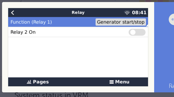
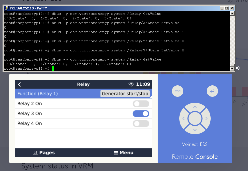
I successfully enabled 3 additional relays on RPI running latest stable Venus OS but only first two are visible on GUI.

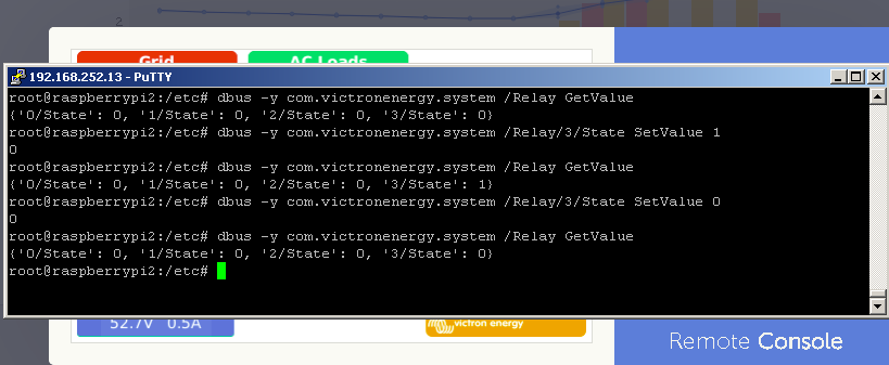
The other 2 are fully functional using CLI dbus Set/Get.

Is it possible to make them all visible on GUI and how?


Thanks,

Mihai

Venus OSRelay
relays1.png (21.3 KiB)
relays2.png (27.2 KiB)
7 comments
2 |3000

Up to 8 attachments (including images) can be used with a maximum of 190.8 MiB each and 286.6 MiB total.

Rob Duthie avatar image Rob Duthie commented ·

Hi Mihai

What is the procedure to make the other 2 relays go i can see four in the gui the last two are blank won't switch on , i had added all the files as per txt below etc.

Is there a order they should be installed in or sim linking files? running Ver 2.40.45

Just adding those change to the files is not correct for ver 2.40.45.

What is the correct order of doing this?new-text-document.txt

Regards

Rob D

NZ

0 Likes 0 ·
mihair avatar image mihair Rob Duthie commented ·

Hi Rob,

You should first try to test the relay functionality before enabling the toggle button on GUI.

Please wire a low current LED in series with 4k7 resistor between ground and your designated GPIO port for Relay 2 and issue the following commands to power ON and OFF the LED :

# dbus -y com.victronenergy.system /Relay/1/State SetValue 1

# dbus -y com.victronenergy.system /Relay/1/State SetValue 0

Warning: DO NOT wire a relay directly to any GPIO output port! Always add an open collector NPN transistor as buffer and a reverse biasing diode in parallel with your relay (as in the following link, Driving a relay)

https://elinux.org/RPi_GPIO_Interface_Circuits

0 Likes 0 ·
Rob Duthie avatar image Rob Duthie mihair commented ·

Hi Mihai

I am PCB electronics design engineer and know to design circuits etc.

I am designing a HAT to include for the raspi PSU 10-55v input, DIO Temp,Tank, Relays

allowed for 4x but have two going OK now, just want to add the other two as i see it has being done and confined, I am running the latest ver 2.40.46 which seems to have issues with the number of relays it can use?

This is a open source design which will be availble to all who want to use it.


So trying to find the correct way of installing the software to make the other 2 work.

I have used your added files to but appear to to activate the remaining two relays.

As per my attached TXT file in my last blog above


Can you advise if it work OK on the latest version.


Regards

Rob D

NZ

0 Likes 0 ·
mihair avatar image mihair Rob Duthie commented ·

For helping you I can not see other option than putting here my modified /opt/victronenergy/gui/qml/PageSettingsRelay.qml file

Keep in mind that I am not running a beta Venus OS version and after modification you must restart the OSPageSettingsRelay.txt

Did you checked the relays functionality as I asked in previous post?


0 Likes 0 ·
Rob Duthie avatar image Rob Duthie mihair commented ·

Using username "root".
root@192.168.1.67's password:
Last login: Thu Dec 12 00:54:07 2019
root@raspberrypi2:~# dbus -y com.victronenergy.system /Relay GetValue
{'0/State': 1, '1/State': 1}
root@raspberrypi2:~#
This is all i get back, if i add the other relays, i just get errors coming back.

I did the symlink and removed /etc/rcS.d/S90gpio_pins.sh, reboot and run the script manually and see what it reports back above.

When i check the Dev/GPIO folder all the relays are there from 1-4.


There must be a sequence this is done in?

0 Likes 0 ·
mihair avatar image mihair Rob Duthie commented ·

Hi Rob,

Last night I had a little bit of time and upgraded VenusOS to latest ver.2.4

It seems that is not possible anymore to add more than two relays based on the procedure described at the beginning of the thread, as in the previous stable version

Adding gpio pins as output in /etc/venus/gpio_list file and running the /etc/rcS.d/S90gpio_pins.sh correctly create the driver files but not the dbus entries.

I am able to control the relays in the following way, but NOT from GUI or with dbus -y command

# echo 1 > /dev/gpio/relay_3/value

# echo 0 > /dev/gpio/relay_3/value

Right now I am not skillful enough to debug dbus problems but I am on learning curve

adding @mvader (Victron Energy Staff)


0 Likes 0 ·
Rob Duthie avatar image Rob Duthie mihair commented ·

Hi MihaiR

That is what i thought, as i have solved most problems with getting the raspi to do most things, which i have. The extra relays would have being a bonus as i was trying to help Mark out with a new Hat i designing to include the extra relays. I will still add at this stage. as it is possible and has be done, just a matter of time and someone with coding experience can sort it out. I am not a coding person but mainly a PCB hardware designer , and part time coding learning to be.

Note: i have tried the older ver 2.33 it worked OK, but the later version no, something has changed. I have noted they have a new GX controller called the Cerbro, which has only 2x relay ports.

Thanks for your help to date.

Regards

Rob D

NZ


0 Likes 0 ·
4 Answers
mihair avatar image
mihair answered ·

Solved!


I just modified /opt/victronenergy/gui/qml/PageSettingsRelay.qml and now is working :-))

On top of the script you have to add:

property VBusItem relay2Item: VBusItem { bind: "com.victronenergy.system/Relay/2/State" }

property bool hasRelay2: relay1Item.valid


property VBusItem relay3Item: VBusItem { bind: "com.victronenergy.system/Relay/3/State" }

property bool hasRelay3: relay1Item.valid


and on the bottom the following lines:

MbSwitch {

id: manualSwitch2

name: qsTr("Relay 3 On")

bind: "com.victronenergy.system/Relay/2/State"

show: hasRelay2

}


MbSwitch {

id: manualSwitch3

name: qsTr("Relay 4 On")

bind: "com.victronenergy.system/Relay/3/State"

show: hasRelay3

}


relays3.png (58.2 KiB)
3 comments
2 |3000

Up to 8 attachments (including images) can be used with a maximum of 190.8 MiB each and 286.6 MiB total.

Mark avatar image Mark ♦♦ commented ·

Very nice work!

0 Likes 0 ·
jeroen avatar image jeroen ♦ commented ·

Can you mark that as an answer to yourself?

0 Likes 0 ·
jeroen avatar image jeroen ♦ commented ·

strictly speaking you need to fix the number in these:

property VBusItem relay2Item: VBusItem { bind: "com.victronenergy.system/Relay/2/State" }
 property bool hasRelay2: relay1Item.valid

 property VBusItem relay3Item: VBusItem { bind: "com.victronenergy.system/Relay/3/State" }
 property bool hasRelay3: relay1Item.valid

but it will work without that for you as well.

0 Likes 0 ·
Rob Duthie avatar image
Rob Duthie answered ·

Hi

Just a question, does it have show a function (relay)1, 2, 3, 4 to operate and assign the correct port for each function like generator for 1 tank pump for 2 etc?

As it only shows function (relay1).

2 comments
2 |3000

Up to 8 attachments (including images) can be used with a maximum of 190.8 MiB each and 286.6 MiB total.

mihair avatar image mihair commented ·

You can assign a function only to relay 1. For the rest of them only manual access via GUI or one could assign a function through CLI scripting

0 Likes 0 ·
Rob Duthie avatar image Rob Duthie mihair commented ·

Hi

What is the procedure to make the other 2 relays go i can see four in the gui the last two are blank won't switch on , i had added all the files as per txt below etc.

Is there a order they should be installed in or sim linking files? running Ver 2.40.45

New Text Document.txt

0 Likes 0 ·
mihair avatar image
mihair answered ·

After some investigations I feel that any relays over 2 was on purpose disabled by Victron in the latest Venus OS version . I presume a simple reason, there are no commercially products with more than 2 relays capabilities.

Anyway, here is an workaround:

For any additional number of relays over two, the relay definition in /etc/venus/gpio_list must be different than standard syntax relay_n. There will be no dbus support for those relays

In this way, after reboot the system will not become unstable and you can control the additional relays as in any other RPI project:

switching on: # echo 1 > /dev/gpio/relay-3/value

switching off: # echo 0 > /dev/gpio/relay-3/value


My apologies to Victron team if this presumption proof to be wrong.

6 comments
2 |3000

Up to 8 attachments (including images) can be used with a maximum of 190.8 MiB each and 286.6 MiB total.

Rob Duthie avatar image Rob Duthie commented ·

Hi

I have found that this folder is missing the extra relay files gpio for gpio22, gpio27

in Ver 33 all is there, but in later versions these are not added at all only the ADC and 2 relay files gpio 21, gpio 17, would this be the cause?

/sys/devices/platform/soc/3f200000.gpio/gpiochip0/gpio

So the work around makes it active again?


0 Likes 0 ·
mihair avatar image mihair Rob Duthie commented ·

No. The python scripts responsible to relay control was dramatically changed.

In ver.2.33 there are routines capable to autodiscovery any number of user defined relays.

example: /opt/victronenergy/dbus-systemcalc-py/delegates/relaystate.py

In the latest version there are only two relays defined

One with adventurous spirit can try to copy the python files from previous version to latest and see what happen :-)

0 Likes 0 ·
Rob Duthie avatar image Rob Duthie mihair commented ·

Hi

I will give it ago nothing to lose. Just had look yes the file size between the old version is very different in size, they have cut lots out in the latest version for both relaystate.py and pyc files.

0 Likes 0 ·
Rob Duthie avatar image Rob Duthie mihair commented ·

Hi

Cracked it all good now, have full operation of all relays and is stable.

Thanks for the advise of were to look.

i will advise Mark as he was having trouble after the changes.

I can now do the HAT with full relay control etc, will be posting the design soon.

Regards

Rob D

NZ

0 Likes 0 ·
jeroen avatar image jeroen ♦ mihair commented ·

The source of the script is here, https://github.com/victronenergy/dbus-systemcalc-py/blob/master/delegates/relaystate.py#L26.


It should actually be able to detect any number of relays, what seems to be broken is requesting the initial state, so it can be restored after reboot. That shouldn't be limited to two. I don't know the details though, but https://github.com/victronenergy/dbus-systemcalc-py/blob/master/delegates/relaystate.py#L37 should return all relays and that is intended behavior. I guess it should be rather straightforward to do something similar in get_settings instead of hard coding it.

0 Likes 0 ·
Rob Duthie avatar image Rob Duthie jeroen ♦ commented ·

Hi Jeroen

All i did was replace the new relaystate.py with the old version from 2.40.33 and it all runs fine now with any number of relays selected and stable.

Regards

Rob D

NZ


0 Likes 0 ·
fguiot avatar image
fguiot answered ·

I'm working on adding some relays on a Cerbo GX, connected externally through Modbus serial interface.

The above procedure is assuming the relays are physical controlled with the rpi gpio. Would it be possible to get the same result, displaying the external relays on Venus GUI?

Thx in advance for any hints, I'm stuck.

2 |3000

Up to 8 attachments (including images) can be used with a maximum of 190.8 MiB each and 286.6 MiB total.

Related Resources

Victron Venus OS Open Source intro page

Venus OS GitHub (please do not post to this)

Additional resources still need to be added for this topic