Hi guys,
I'm completely stuck. I've got a Venus GX on my bench that I'm trying to interface to an Eltek SmartPack S battery charger via Modbus TCP. I was told that Modbus is really easy to use, but my experiences are far from it.
So far, I have the Venus GX set to Modbus enabled, and on the Eltek unit I've set it to allow the GX's IP. But I have no idea how to get them talking (they're on the same physical network/subnet).
Everything I read online points to the CCGX Modbus TCP Register List, but that's just a bunch of stuff that I don't understand (yet) - nor can I find out where to enter such values. Surely other people are stuck on the basics? I've never used Modbus before, and have searched these forums and Google extensively, but can't figure out how to even get the Venus GX communicating to another device.
I really like the Venus GX units and we've started deploying them on all sites including solar etc. Using CAN bus on them is super easy, as with VE Direct etc.
Could someone point me in the right direction? I've got the Eltek charger on loan pending if I can get this working - I've got a box of about 10 Venus GX's here and another 100 or so more to order if I can get them doing what I need them to!
Thanks,
Richard.
asked
Modbus TCP Basics
Bump. Does anyone know how to do this?
I've moved this to the modifications space where there is more experience with Modbus.
While you wait, Try reading through the Modbus Community Topic.
Your reply is no help whatsoever. I've read the Modbus topics and cannot find answers to getting things to link up.
Also this is hardly a modification; Modbus is part of the GX system.
Maybe I ditch the Victron units and find another manufacturer if nobody can help me. Given the quantity of these we're planning to purchase (we're a telco operator) I would have thought Victron would be of more help.
Sorry I can’t be of more help with this. Matthijs explains the situation a bit here: https://community.victronenergy.com/questions/10881/launching-the-mods-space-a-new-section-on-communit.html
Modbus TCP is one of those areas of the product range that is enabled, and encouraged but is unable to be as completely documented as the core functionality (Eg battery charging states).
This modifications space moves more slowly than the general Q&A, and tends to interest those that have more specific knowledge of these deeper technical areas of the products potential.
If you still have further need of support for a large commercial project, you could also try to contact the Victron Sales Manager in your area - https://www.victronenergy.com.au/contact
Thanks to Alistair also for the information.
Hi, Which aspect of the communication are you struggling with? Have you established any data transfer yet? Have you tried a Modbus simulator to read data from the Venus unit? I am more than happy to help you get started. Tell me where you're at and we'll go from there!
Rob
Modbus is easy... it is a protacol standard applied to various physical networks that standarises how numerical, mostly, data is exchaged.
It is a client server architecture so any given network will have a single master and 1 or more slaves.
The master, client, contacts slaves, servers, one at a time either asking for data or sending data.
The protacol is quite old and has some legacy terminology asosciated with it, coild for example are single bits that can be on or off, think relay coils. Registers represent numbers, originally 8 bit integers, but now typically 16 bit intergers, with the option to treat as signed / unsigned and pick the byte order amongst other things.
In practice ask for just ask for some value you know and fiddle with the bits you dont know the setting for until you get the value you are expecting.
In short the device you are asking to give you info is is a slave/server that expects a properly formatted question from a master/client and will respond with an answer that is the contents of one of its registers... Or will accept a value making its register equel to it and then confirm it has done that.
You can test modbus TCP, the kind that occurs over ethernet, as opposed to a serial interface which is modbus RTU or ASCII, using a small windows master application.
Just look Windows Modbus test application.
If yiu give me speciffics I can probably help more.
Al
To add to what Alistair says.
For the CCGX, if you want to read a value then you will be want to Read Holding Registers (Function Code 03). The TCP Register List, which you have seen, is vital for deciding what Unit ID and Register to address.
There are various Unit ID's which you need to to know in order to access the bit of equipment that you want to query. The "Unit ID Mapping" tab will guide you on this one. The look up the "Field List" to get the parameter that you want.
The Eltek should have its own documentation for it's specific implementation of Modbus. It should have the information about how to form the queries that you want to direct at the CCGX.
Simply MODBUS is an excellent resource if you are new to the Modbus Protocol:
http://www.simplymodbus.ca/index.html
It really is quite easy, it's simply a query and a response is returned.
I just ran some tests using Virtuino Modbus console for android. cant comment on it but it works as a test console and has pretty switches and displays... Dont know if can run scripts, just wanted a configurable testbed.
As I said in another thread, the victron documentation seems a bit light and less than clear but a bit of fiddling returned some figures and allowed me to turn the generator on and off using Modbus.
(search 'generator running indication' for my post with details)
I suspect MQTT with some form of HMI/script engine combo, node red perhaps, would be a reasonable way to go but then a PLC with a Modbus HMI has considderable merit too, and would likely be more stable than some cheep box from accros several sea's.
To be fair the HMI bit is almost an asthetic choice, given a few basic prerequisits the question is on what to run the script engine and which one?
I expect that Modbus will have a bigger overhead network overhead than MQTT simply because it requires continual polling where MQTT is event based.
Sorry... off topic... New topic I think.
Thanks for the replies everyone; I'll definitely have a look at the Windows Modbus program to see what I can read and write. Also thanks for the Simply Modbus link too.
I'm working away from the office today, but I'll have a look into this in more detail on Monday. I've also got the Eltek rep coming on Tuesday so that we can sit down to try and nut this out!
Will be in touch with my findings after the weekend.
Cheers!
Richard.
Fundamentals... and I am not having a pop at all but you need to grasp the concepts before it all falls into place and make sense...
1 They will not just talk, it dosnt work like that.
The GX is a server, slave in Modbus terms, which means it serves data, or accepts it, as values in a register, that the list of values you are talking about, its a bit like a house number and postcode.
To get data from or write data to the GX you have to have a client that is configured to ask questions or send requests.
Obviously to do this the client, typically called a master, needs to know where to ask the question and precisely what to ask... Then it needs to know how the data is formatted so it can scale it.
2 It sounds like you have two slaves... Not an option
If the Eltek cant be configured as a master, with all the info a master needs to ask a seriese of questions, then you will need a seperate master to broker and transfer the data.
Modbus is inherently simple, usually, and very robust, but it is strictly simplex comunication with one master talking to 'some' slaves one at a time.
Generall stuff
If you are using a serial interface it is likely to be RS485, although there is technically no reason some that other physical standards cant work, and in this case the subtype will be RTU, as opposed to ASCII.
If you are using Modbus TCP it is generally even easier as the ethernet standard and TCP stack will handle everything in the background, other than addressing, which in this case would be the IP address of the GX and a device ID, which may be called a drop number in some clients, that the GX will use to send your query to the corerect device.
A single modbus device needs an address/drop number, so that it can listen and respond to requests sent to it. When using Modbus TCP a single device is addressed on the network by its IP address and many compleatly ignore the device ID,
The GX however is technically a Modbus gateway which is slightly different...
Its IP address gets your request to it and when it arrives the gateway needs to know which physical device to forward that request to. In the GX ID 0, or 100 which are the same, is the system, the GX its self.
Everything else either connects on a multy drop bus and will have its own unique ID or is connected on a direct serial port, where the device responds to all requests but the port has an ID
In both cases the ID is the route through the gateway at a given IP address. 'The house in the postcode...'
Given that I have only been looking at this stuff for a few hours I have probably oversimplified and may have missed some stuff but the basics are correct, I know because I have just tested them.
I just had a quick look at your device and from a quick skim read I couldnt see anything suggesting it was capable of acting as a Modbus master. It definatly supports TCP and RTU as a slave, which would be typical for instrumentation designed to be read by a master of some sort.
I coud be wrong but I am pretty sure you are going to need an aditional lump of kit, a small PLC would be Ideal, to pass formatted date between the two devices,
It is possible, although not likely, that th two devices will be running a different data standard and cant talk to a single master. However as the Eltek also supports RTU, presumably over RS485, that wouldnt be much of an issue as the PLC coud use physically different interfaces to talk to each of them.
Have a look at a schneider M221CE16T or M221ME16T
Those would almost certainly handle the comunication needs and also provide physical IO
(Note that there is a limit to the number of blocks read which is 32 I think but even that can be circumvented if needs be.)
They are solid, reasonably priced and he programming software is FOC. Iam suggesting them because it is what i usually use, there will be many other options from many suppliers.
Thia is what I would be using if I dint need MQTT for other stuff as well as this, I may go that way anyway for the genertor interface, as the PLC will handle all the generator automation needs including choke positioning and speed sensing without the need for additional interfaces.
Interestingly as MQTT is text based it will probably be possible, if a little messy, to get the PLC to talk to the MQTT broker by adding a serial IP converter as an interface.Off topic sorry.
I can probably give you speciffic help if you need it, but I MUST state I am not a victron expert by any means. I do however build control systems for hydro sites and regularly design interfaces for industrial equipment of various types.
Hope that helps,
Al
Hello Victronauts!
I was doing some research for MODBUS because I want to connect a Siemens Logo! with the Victron ESS system to do some controlling of external loads as a Wallbox for charging EVs. As knowing nearly nothing about MODBUS the explanation here, was very helpful.
I used the above mentioned Windows software "Simply Modbus" and the Victron excel sheet from the Whitelist section and time to play and test with the software.
More and important information about MODBUS you will find in GX-Modbus Manual.
At the end it was quite simply. Here as example what I did. Perhaps it is helpfully for somebody and saves time.
As a first test I wanted to get from com.victronenergy.system the values for AC consumption L1-L3 and Grid L1-L3.
Based on the excel sheet it is unit-id: 100 and register 817, 818, 819, 820, 821, 822 - as I wanted to see more registers I read in one run 15 registers from starting 808 to 822. For reading registers you need function-code 3 (see: Modbus-manual)
Here is a screenshot of the above software, the excel spreadsheet and the remote console.
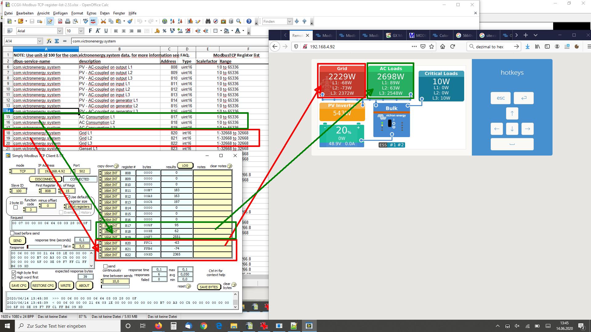
- You can click on the image to enlarge it for better viewing.
The values in the remote console are a little bit different than the results thru modbus because for doing the screenshot I needed some additional time.
I wish success with modbus
DayAndNight
What is the purpose of different dbus-service-names in Modbus context?
com.victronenergy.system
com.victronenergy.vebus
com.victronenergy.battery
com.victronenergy.solarcharger
com.victronenergy.pvinverter
com.victronenergy.motordrive
com.victronenergy.charger
com.victronenergy.grid
com.victronenergy.settings
com.victronenergy.hub4
com.victronenergy.gps
com.victronenergy.tank
com.victronenergy.inverter
com.victronenergy.genset
com.victronenergy.temperature
com.victronenergy.pulsemeter
com.victronenergy.digitalinput
com.victronenergy.generator
com.victronenergy.meteo
com.victronenergy.evcharger
com.victronenergy.acload
com.victronenergy.fuelcell
com.victronenergy.alternator
com.victronenergy.dcsource
com.victronenergy.dcload
com.victronenergy.dcsystem
com.victronenergy.multi
I understand that if I have a GX device, say Cerbo these days - it has unit-id 100 and Excel sheet's Modbus register addresses are found behind that unit-id when queried. Quattro II has unit-id 227.
GX-device and inverter have different unit-ids and different set of registers and provide different set of information.
But what is the difference between system, vebus, charger, grid, hub4, inverter, genset, generator, multi etc? Many of them have AC L1 {voltage,current,power} for example and these seem to exist under different dbus-service-names and hence overlap.
When creating a virtual, multi-phase system with multiple inverters - that could explain 'system' having the combined information. But that doesn't explain all the overlaps that the Excel list has. @DayAndNight
Edit:
Cerbo console: Settings -> Services -> Modbus TCP services
Quattro-II 48/5000/70-2x50
com.victronenergy.vebus:       Unit ID: 227
.
.
com.victronenergy.system:      Unit ID: 100
com.victronenergy.generator:   Unit ID: 100
com.victronenergy.hub4:        Unit ID: 100
That still doesnt' explain the difference between Cerbo's system|generator|hub4
This is a super nice of you to pull this graphic together dayandnight. i have a cerbogx, smartsolar and mutliplus II and i am able to talk to the cerbo on slave 100 and the smartsolar on 224 but i can't find any way to talk to the multiplus II. i want to be able to change the maximum current setting which is not available with the 800 range of commands available on the cerbo but i can't find any way to get a response to anything else. my control panel says the multiplus is on slave address 227 but i tried everything i could from the spreadsheet and didn't get a response. any suggestions?
greg
ok skip that. i tried all day then as soon as i posted this i got it working. it is slave address 227 but using the ve bus commands. i can not remotely control all of the multiplus ii functions. This victron stuff is really slick. i wish it weren't so loud but the automation is really nice.
greg
Having a first go at modbus today - people learn in different ways, maybe the below can supplement the v useful info above ...
A simple starter using a RPi4 (assuming you have a CCGX running on your lan).
Install pyModbusTCP: sudo pip install pyModbusTCP
In Thonny:
from pyModbusTCP.client import ModbusClient
c = ModbusClient(host="192.168.1.<your CCGX IP address>", port=502, unit_id=100, auto_open=True)
regs = c.read_holding_registers(817, 3)
if regs:
<indent>print(regs)
else:
<indent>print("read error")
... select Run and you should see the system AC Consumption on L1. Details about the unit_id and 'registers' in the excel sheet linked to above. As others say above, that's all there is to it!
Hello
nice thread. thanks for the pic with mapping and explanations.
I am writing a c# programm and querying aprox. 50 modbus values from 5 start adress ranges.
Does anyone nows the minimal query time to the GX gateway? I fear to crash the gx with to many modbus pollings per time. I have seen several failed devices (EM24, Hoymiles HM1500, Pylontech US3000C) from other OEM, when I was polling every second a range of modbus registers via TCP.
thanks in advance
Thomas