question

dognose avatar image
dognose asked

ESS as "Subgrid" / Fronius Hybrid with BYD Battery present

Hello,

i'm currently running a little unusual setup, but got everything working (technically) it seems. However, I'm not 100% satisfied and not sure if this arrangement may cause any issues - So i'm searching for ideas how to improve this (or notes if there are any safety concerns, of course)

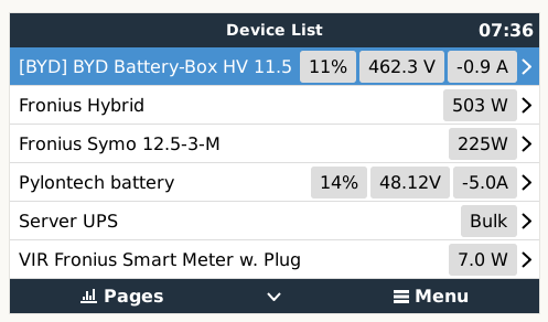
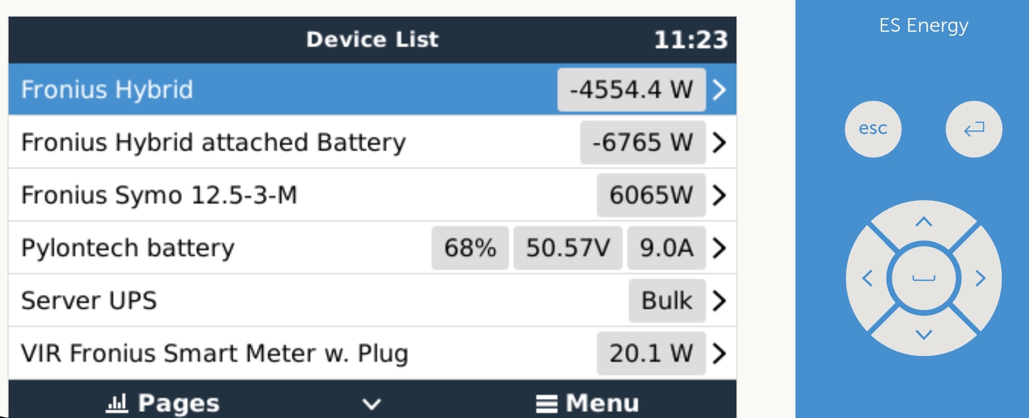
First, I'm running 2 Fronius PV-Inverters. One is a Regular Symo (12kW) and one is a SymoHybrid (5kW), which also has a 12.4 BYD Battery Box (HV-Battery) directly attached. This battery is lasting almost through the night for our self-consumption, which lead to the current improvements:

I'm having a Server-Rack, hosting everything relevant for my home and business. Servers, Switches (Poe) and so on. The general load of our home is 800 Watts, where a constant 300 Watts are dedicated to that server Rack. Now, recently my UPS died and a new one with lead batteries seems like yesterdays news. So, I decided to go for a Multiplus 48/800/9 and a Pylontec UC3000. (~3.5 kWh)

This works fine as UPS, and also servers a total runtime of about 12hours. So, my thoughts are to use that second battery to support the main battery as well. Going down to like 25% every night still leaves plenty of UPS-capabilities to shut down servers savely in case of a Power-Loss.

I've also used a script found on github (https://github.com/ayasystems/dbus-fronius-smart-meter) to add the fronius smartmeter to the cerbo, which works nice.

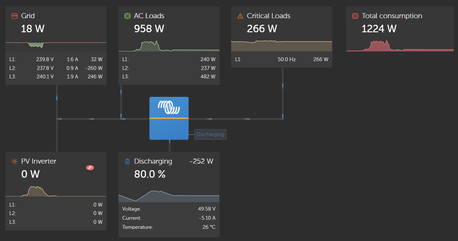
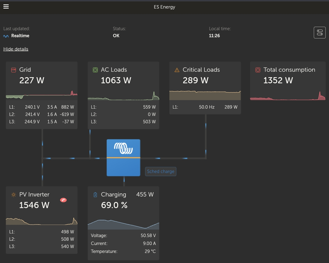
So, with all setup, the overall image in the VRM Portal looks like that, where the BYD Battery is connected directly to the PV-Inverters and not visible - and that is the point that is causing a lot of issues, will explain bellow:

duringdaycerbo.png


duringday.png


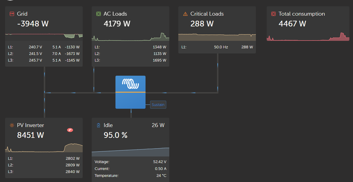
The ESS is perfectly fine charging the second battery from solar in this situation. However the first problem is the invisibility of the BYD-Battery connected to the Fronius Hybrid inverter. It will result in a constant "view" that the PV-Inverters are delivering like 800-900 Watts even at night - which causes the ESS to do nothing with it's own battery, because obviously it is assuming that there is enough Solar-Power available:

duringevening.png


So, my first attempt was to play arround with ESS Mode 3, and manually force the victron to discharge. But forcing it to discharge seems only possible, by setting the desired "Grid setpoint". Since both Inverters (Fronius Hybrid and Victron) are now trying to fullfill their goal, it is leading to a constant "battle" of provided AC Voltage. Not satisfying, efficent and maybe not even healthy at all.

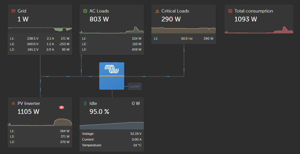
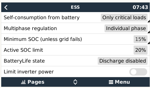
In ESS there is the option to set the Grid-Metering to "Inverter/Charger" rather than "External Meter", so while this sounds like exactly what I need ("The inverter would determine it's Grid-Pull and use it's battery to 0 that as grid setpoint), the manual unfortunately states, that for this setup, any PV-Inverters have to be connected to AC-Out - which they aren't and obviously can't.

So, to have ESS working correctly, I added a Shelly Plug between the Multiplus and my "Home-Grid" (https://github.com/Telekatz/venus.dbus-shellyPlug/), removed the Shelly Smartmeter Script, set the Shelly Plug to act as Grid-Meter - and finally also removed the Hybrid inverter.

This now leads to the BYD-Battery becoming invisible, and the inverters ESS acting like it is it's own tiny island, only charging of solar when the 12kW inverter says that there is enough power. However, due to removal of the fronius smartmeter, remaining AC Loads and actual Grid-Consumption become invisible as well. This is sad, cause I really like the VRM.

gridhack2.png

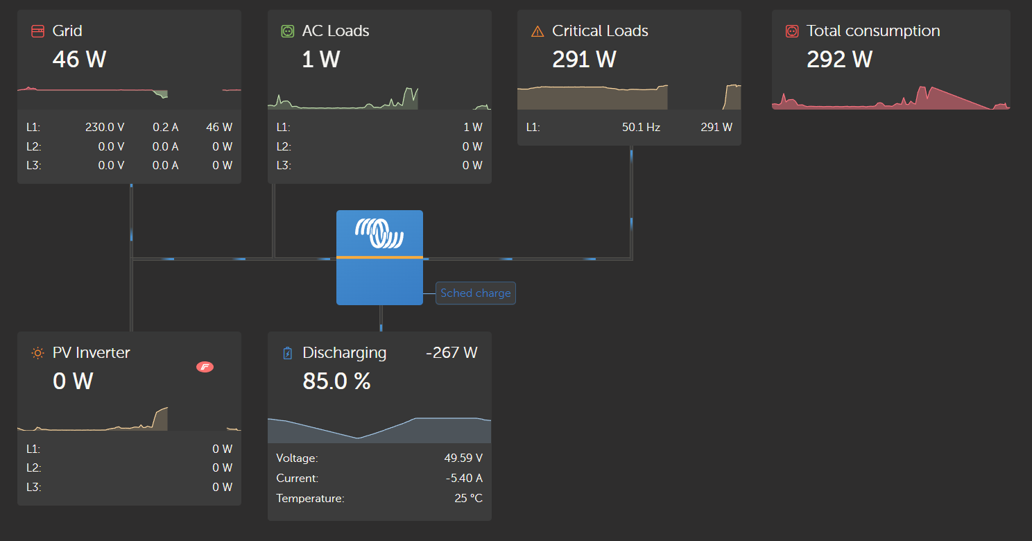
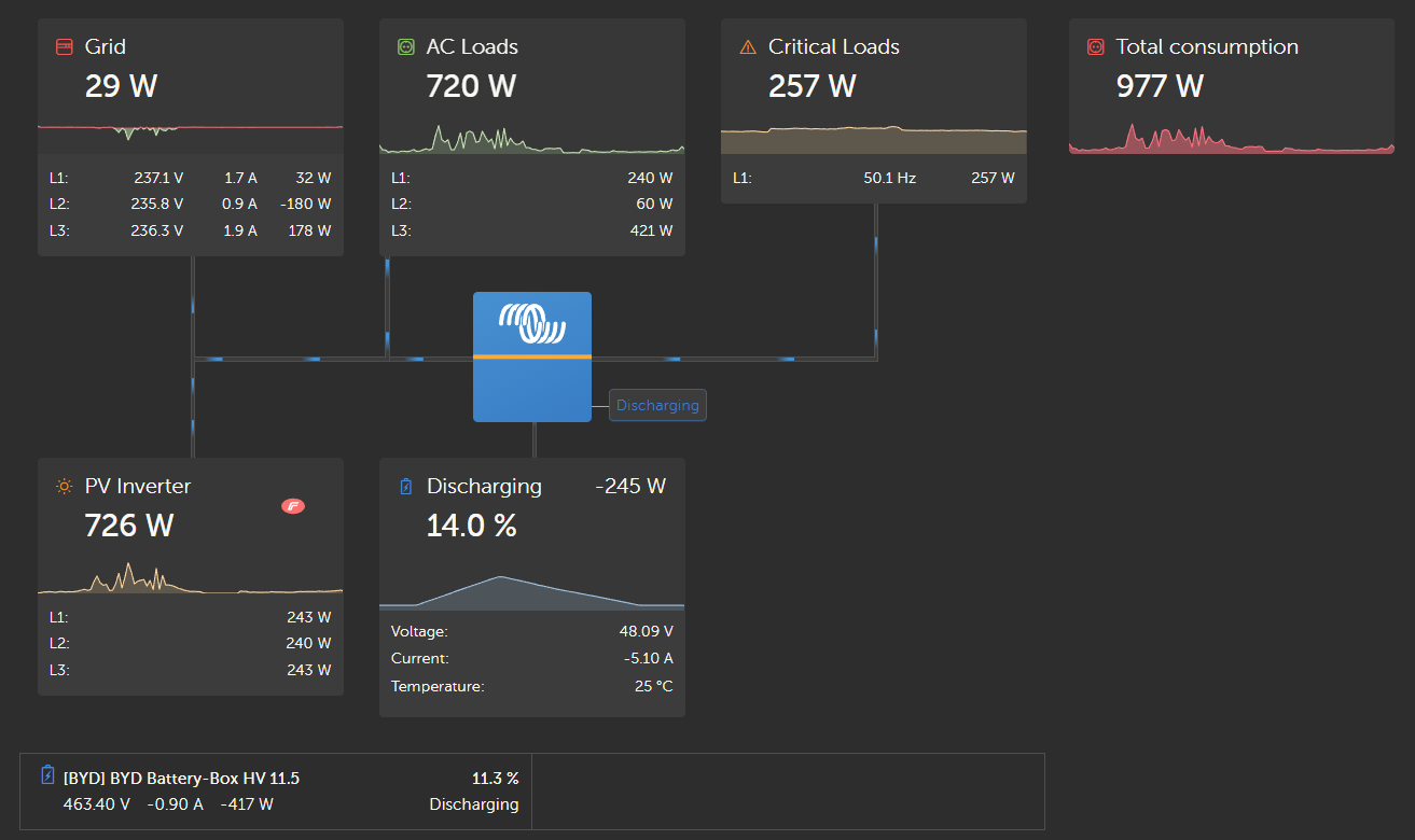
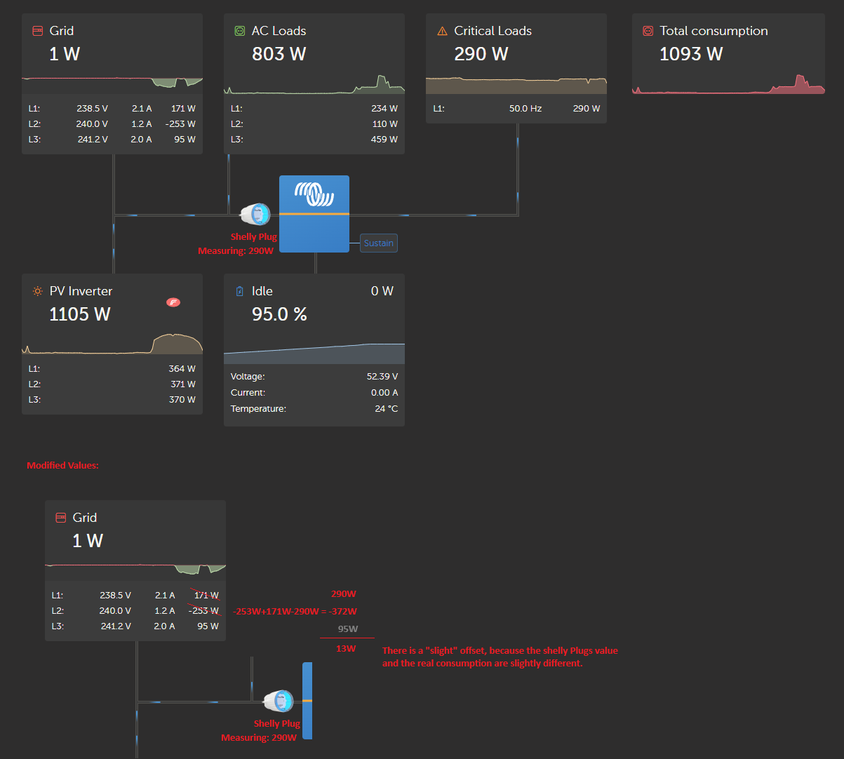
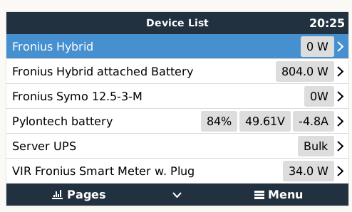
The image now is "slightly" Wrong, regarding the meter, it would actually look like this:

gridhack3.jpg

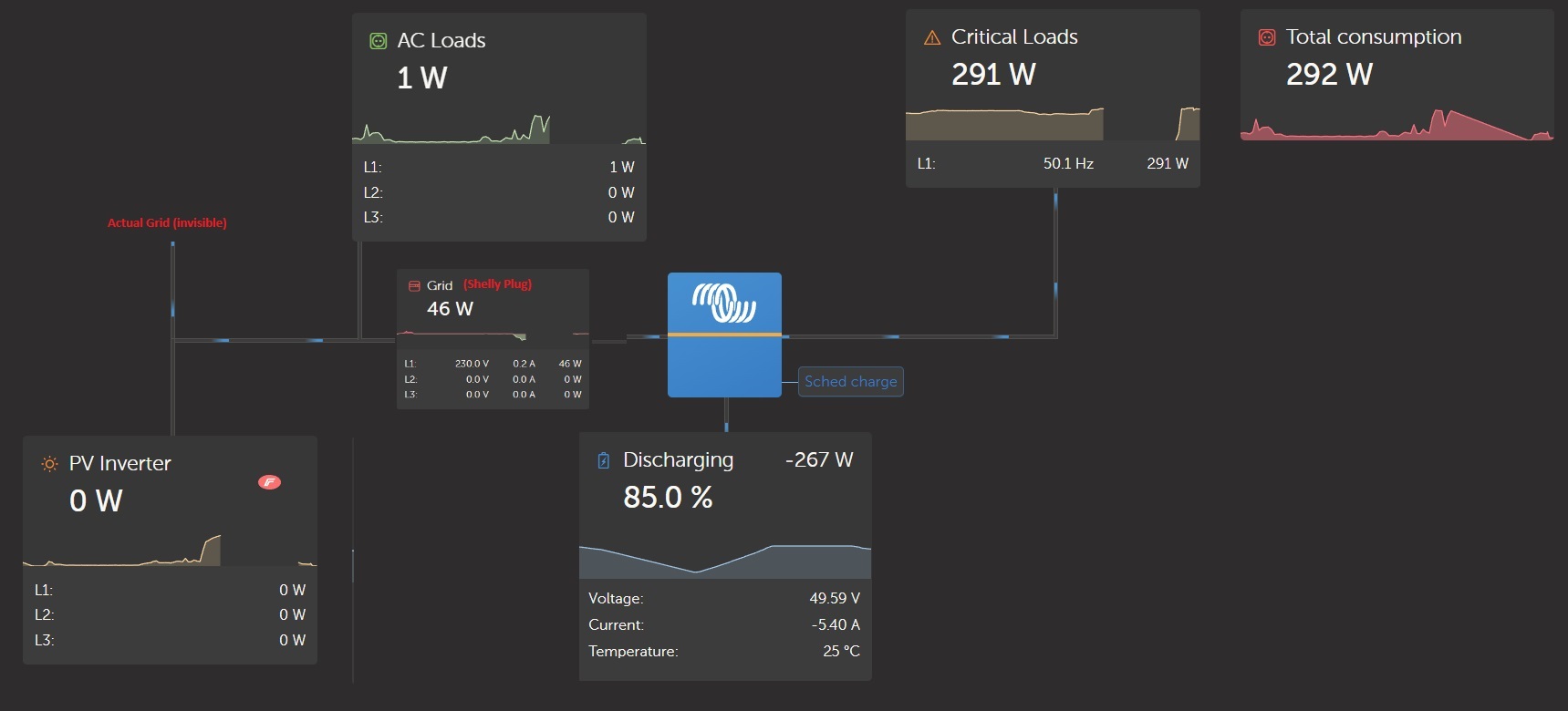
I've also set the "Grid Setpoint" to 30W to ensure there is a constant pull on the AC-IN of the Multigrid. Not sure if required, but makes me feel to have more control over the energy not flowing "backwards". (I've also set to only support Critical Loads with Power, but in ESS Mode 3, I got it to feed in 600 Watts, so not sure if that option is working correctly)

---

Yeah, so I got It working as expected for the moment. But as you can see from the missing information it is not satisfying with regards to the VRM display.

Any Ideas, if this setup can be operated with ESS, while having the Hybrid Inverter, Fronius Meter and BYD Battery beeing shown as well?

I'm a software engineer, so if that is not working out-of-the-box, my next approach would be to reverse engineer the scripts for the fronius-meter / shelly plug and adapt them to create 3 new versions:

1) Injecting the hybrid inverters power MINUS battery feed in.

2) Show the Battery-Feed-In from the BYD-Battery, maybe as a Generator, or whatever else can be "added" on the AC-Side through dbus. (At least I think that ESS then would say: "Okay, 0 PV Power, 800 Watts from Generator only - so we discharge and don't charge")

3) Also I would need to mess arround with the smart-Meter script to inject the shellies Value as Phase1, while adding the original Phase1 Value (minus shelly plug) to Phase2 to get a correct "total". That way, the Multigrid could "balance" on the reading of L1 of what he thinks to be L1 of the grid meter, while in realty he only balances with regard to the shelly and the grid meter is actually handled by the fronius Hybrid (which does does this independent of the VRM / ESS).

But I would prefer a solution that is a bit less hacky :)

ess dischargingfronius symopylontec
duringday.png (62.9 KiB)
duringevening.png (59.1 KiB)
gridhack2.png (76.2 KiB)
gridhack3.jpg (100.1 KiB)
2 |3000

Up to 8 attachments (including images) can be used with a maximum of 190.8 MiB each and 286.6 MiB total.

7 Answers
dognose avatar image
dognose answered ·

While waiting for Moderator Approval, I've digged into existing python scripts, and modified them to my needs :)

To make everything work "smooth", there were 2 major Issues to address, both are solved with the respective dbus services:

1) When having the multiplus / ESS running of the fronius grid, it is "hard" to have a steady feed-in of either battery system. The Fronius will balance on all 3 phases of the grid to achieve a "0 Watt" in Total - that could be anything on Phase 1. And the ESS will more or less also try to balance on the grid meter, so both devices are constantly interfering with each other.

2) The original victron implementation of Fronius inverters shows the battery discharge of a hybrid as PV-Output. This leads to ESS not discharging it's batery, and even charging of the battery-feed-in of the hybrid, which in turn will provide more feed in and so on.

-----

A1)

The script to address Issue one is now available on Github. There is also a dedailed description, whit images and so on. As a short summary, what it does:

It manipulates the values read from the fronius smart meter and presents a Phase1 that equals the consumption of the ESS-Subgrid only.

In Order to achieve this, the Script performs the following manipulation on the actual Smart-Meters values:

  • Value of L1 is replaced with the value measured by the shelly Plug. This allows the Multigrid-ESS to work on L1 as grid set point, without "fighting" against the Fronius Hybrid. Make sure you configure ESS to work in individual phase mode, so it only considers "L1".
  • Original Value of L1 is added to L2.
  • Value measured by the shelly plug is deducted from L2, so the incoming/outgoing total stays the same.

https://github.com/realdognose/dbus-fronius-smart-meter-with-phase1-injection

1713124098545.png


A2)

The original Implementation of Victrons Fronius Readout shows all Fronius inverters as PV-Inverters. With a Fronius Hybrid including a battery, the energey coming from the battery is simply shown as PV-Output. [...]

So, I wrote my own script, that addresses two issues:

  • The Fronius Hybrid Inverters PV Output will now be shown as it's regular PV Output MINUS Battery charge. (That is PV-Input we don't have available to ESS)
  • When the Fronius is Discharging, it's AC Output will show 0, so the ESS starts to behave correctly with the knowledge that there is no PV-Power.
  • Now, the victron system will miss the AC-Loads - so, i've added a genset called "Fronius Hybrid attached Battery" that will show the actual discharge amount. When running with AC1 set to grid, the generator won't be displayed in VRM, but it is taken into account for total AC-load calculation. (While it's positive - the negative value seems to be ignored)

    1713124301808.jpeg
  • (On second view of the first image, the values don't seem to fit together, for a better understanding, let me explain:

    The Hybrid is currently serving around ~ 2200 PV Power. This is going straight to the battery, so the PV Output would be 0. Additionally the hybrid is consuming 4554 watts from AC1, where the 12k inverter is feeding in 6000. So, total available PV Power for ESS will be presented as 6065 - 4554, even if the "actual" PV production is 6700 Watts higher. But since they go directly to the fronius battery, they are not available for ESS.)

1713124280009.png

https://github.com/realdognose/dbus-fronius-hybrid-battery-visualisation
----

Finally ESS is doing what I want it do do:

- If there is (real) PV Overhead, charge the Pylontech battery. 1713124385044.png- If there is no PV Overhead, discharge the Pylontech and feed only Critical Loads. (Minus the 30 Watts I like to have constantly flowing from "home grid" towards "ESS")
1713124415553.png


1713124098545.png (91.4 KiB)
1713124280009.png (26.4 KiB)
1713124301808.jpeg (186.1 KiB)
1713124385044.png (154.9 KiB)
1713124415553.png (79.6 KiB)
2 comments
2 |3000

Up to 8 attachments (including images) can be used with a maximum of 190.8 MiB each and 286.6 MiB total.

nickdb avatar image nickdb ♦♦ commented ·
If you could validate your email address, it is less likely for a newer account to end up in our approval queue. I can resend it if you missed it at signup.
1 Like 1 ·
dognose avatar image dognose nickdb ♦♦ commented ·
Did it again. Seems like I clicked the link, but didn't note that I have to click "submit" on the page again.
0 Likes 0 ·
dognose avatar image
dognose answered ·

Tiny update on behaviour I noted this morning:

With "removing" the PV-Power flowing to the Hybrids Battery, ESS (without charging schedule) would wait until the Hybrids Battery is fully charged (or PV Production is greater than the Hybrids Battery maximum capability), because obviously it would only "see" PV-Output if there is more than the BYD-Battery could consume.

Since the Pylontech is only charged with 9A max in this setup, it takes around 5:45 hours to reach 95 Percent. Therefore, it is desireable that it starts earlier and not waiting until the BYD-Battery is fully charged, especially on days with little PV-Overhead.

This is easy to address with available Options, I've configured a charging schedule to start everyday at 10:15. At that time the BYD Battery is still charging, but the Hybrid Inverter will then reduce the charging current to favour it's "loads consumption".

Here are two snips of my homebrew surveillance dashboard:
- Discharge during night is nice and smoothly distributed between both systems.
- When the Pylontech finally reaches it's minimum USP-Threshold, it stops to discharge and the main battery takes over the full load. No charge of the Pylontech happening at that time cause "PV-Output" stays at 0 due to the own implementation on the inverter readout.
- When the sun came out, charging of the pylontech stayed at 0 for the reasons mentioned above, but then started at 10:15, sneaking some of the power that would otherwise be feed into the BYD Battery at that time.

behaviour1.png
flow.png


behaviour1.png (97.1 KiB)
flow.png (112.7 KiB)
2 |3000

Up to 8 attachments (including images) can be used with a maximum of 190.8 MiB each and 286.6 MiB total.

Michelle Konzack avatar image
Michelle Konzack answered ·

All Fronius Primp/Symo/Hybrid have a POTENTIAL free relais output which can be programmed. E.G. Solarproduction >100W or whatever.


You have nw two options:


1) You can use a Cerbo Digital Input to let the Inverter know, that in canse ofno SolarEnergy it should not such any energy from the "grid".


2) Since POTENTIAL free relais output does not support a hig current, you can use it to switch a HghPower relais to cut the ACin Line of the MultiPlus which has tbe programmed as UPS in this case. This is the simpler solution since you do not need any interventions in the CerboGX

3 comments
2 |3000

Up to 8 attachments (including images) can be used with a maximum of 190.8 MiB each and 286.6 MiB total.

dognose avatar image dognose commented ·
Thx for your suggestion. I thought about this as a "Plan B" to have controlled discharge: Simple put the victron into "emergency power mode", by cutting it's AC connection.


I've already tried this with the installed shelly and controlled by some external script.

It would for sure be an option to make sure that both circuits can provide their battery charge independent, but I like the solution to mess with the L1 value more for a single reason:

Physically cutting of the AC1 connection requires a highly reliable solution to bring it back online when the battery is almost drained. In Case of the shelly plug some wlan issues, script issues or even technical malfunction of the relay may cause a failure here.

Controlled by cerbo through one of the output pins may be more reliable, but would require additional hardware.

The current solutions worst-case "mallfunction" would be wrong charge / discharge but under no circunstances cause any inoperability of the loads attached to the multigrid inverter.

It'll either provide too much power, then going elsewhere or to less power, which then is pulled from AC1.


0 Likes 0 ·
Michelle Konzack avatar image Michelle Konzack dognose commented ·

Regarding:

Physically cutting of the AC1 connection requires a highly reliable solution to bring it back online when the battery is almost drained. In Case of the shelly plug some wlan issues, script issues or even technical malfunction of the relay may cause a failure here.

1) The potential free relays in the Fronius is very reliable since it is also ment to control Heatpumps and such.

2) If the Battery is even 100% drained and the Fronius connect the MultiPlus back to the Grid, then the Batteries are automatically recharged.

3) WHY do you wand to use a Shelly plug? They are highly non-reliable. I have thrown away this crap. Do not work if you have a wall between or the distance goes over 10m.

4) A reliable system is hard wired


1 Like 1 ·
dognose avatar image dognose Michelle Konzack commented ·
I've meanwhile switched to use the AC-IN Value as determined by ESS to calculate "what's going on" . So the shelly plug is no longer required at all.
0 Likes 0 ·
oxident avatar image
oxident answered ·

Very interesting and detailed report! I'm having a similar setup (different ESS brand) but facing the same issues with concurrencies between both ESS when using Mode 3.

My approach was to build a script which tries to dynamically alter the setpoint every few seconds but it got rather complicated, isn't bulletproof at all and still leads to several wasted or bought kWhs per day.

Therefore, your basic idea to strip everything down to L1 and replacing the built-in Fronius monitoring sounds interesting.

2 comments
2 |3000

Up to 8 attachments (including images) can be used with a maximum of 190.8 MiB each and 286.6 MiB total.

dognose avatar image dognose commented ·

Yes, altering the set point alone turned out to be "insufficent" when another battery / inverter is balancing on that value.


So, faking a L1 value, which is only impacted by one of the inverts works well.


And by adjusting L2 as well, overall consumption/feed-in can be restored

0 Likes 0 ·
dognose avatar image dognose dognose commented ·

Also I removed the need for external measurements, by querying the dbus, about the AC-IN value of the multigrid inverter.


I'ts now basically like running in "Inverter feed in point" mode, without running in "Inverter feed in point" mode (plus the fsked feed in / pv overhead I want ESS to work with)

0 Likes 0 ·
dognose avatar image
dognose answered ·

I've now wrote several more scripts for my "cerbo" and got a better understanding of everything - so, I revised both scripts, optimized them and have to correct a statement above:

ad "Fronius-Hybrid-Battery"
ESS is not caring about the shown PV-Inverter output. It seems to have been a Configuration-Coincidence that made me believe this. In fact, the only value it uses to determine non-scheduled charge or discharge is the grid-set-point. Makes sence: If there is feed in? Charge. If there is Grid Pull? Discharge.

So, the script that alters PV Output and shows the battery as a generater has been "changed" so, it now is showing "another battery" that delivers PV Output, as one would expect:

1713455397331.png
1713455407299.png

ad Manipulated Phase1-Meter:
I've now switched to directly use the AC-IN of the inverter rather than a external device to measure consumption. This reduces complexity and therefore increases reliability.

The script now also allows to configure "which share" of available PV-Overhead should go to the ESS managed battery and which share should be left to the hybrids battery. (Set it to 0 to charge the hybrids battery first, set it to 100 to charge ESS battery first)

This now works very well, but is suspect to be improved as well :)

Detailed description in the (not yet finished) readme: https://github.com/realdognose/dbus-fronius-smart-meter-with-phase1-injection


1713455397331.png (69.4 KiB)
1713455407299.png (28.4 KiB)
2 |3000

Up to 8 attachments (including images) can be used with a maximum of 190.8 MiB each and 286.6 MiB total.

oxident avatar image
oxident answered ·

Congratulations to this great work!

I've already tried to adapt it to my situation but I guess it would need a more "generic" way to achieve this goal for other subgrids/external ESS.

In my case, I'm still facing the problem of one battery loading the other. It also sounds quite logically that the Cerbo fails when the external ESS discharges because it also causes an effective grid point of +/- 100W.

At this time, the Cerbo won't stop charging because of it's own desired gridpoint (e.g. 30W) and even increases the charging amount :-(

Maybe a combination of your script and a "dynamic" setpoint could be successful?

1 comment
2 |3000

Up to 8 attachments (including images) can be used with a maximum of 190.8 MiB each and 286.6 MiB total.

dognose avatar image dognose commented ·

Yes, an important part of the script is that the value you are setting for L1 needs to take into account what ESS is already "doing" to reach it's grid set point.

I.e. if you have already 200 watts going to it's battery, the value for L1 needs to take that into account, or ESS will keep cranking up the charge rate till maximum (or feed in to maximum), which then causes a back-and-forth with the second battery.

I think I have the equation "that considers everything" finished right now, all simulations passed, still need some real-world-verification for it. Hopefully get that tomorrow.

Will then post some examples and the equation.

In a very nuttshell: Assuming you use a grid setpoint of 0, you always need to set L1 to the DELTA you want ESS to additionally consume or release, not an absolute value:

- Want 150 additional charge? -> Set it to -150 (ESS thinks theres 150 feed in to consume)
- Want 150 less charge? -> Set it to 150 (ESS thinks there is 150 grid-pull to cancel out)
- Happy with the current charge rate? -> Set it to 0

And ofc, every second/cycle that "desired delta" has to be re-evaluated as the system values changes.

1 Like 1 ·
dognose avatar image
dognose answered ·

Ok, so here's what I finally came up with. It seems to work under all situations in the way I want it to work. First, it is required to collect some data and determine what Excess-PV is available to use.

There is a number of pittfalls there, because some values contain others and some are "not ideal" to work with (i.e. The Fronius Hybrid's battery DISCHARGE is shown as PV-Output) - or the AC-Loads as queried from dbus CONTAIN the critical Loads of the subgrid as well.

The values I (reverse-)engineer are the following. Naming should be somewhat self-explanatory:

logging.debug("AC-IN Victron: " + str(acInESS))
         logging.debug("AC-OUT Victron: " + str(acOutESS))
         logging.debug("AC Loads: " + str(acLoads)) #AC Loads already contains Critical Loads as well
         logging.debug("AC Loads (cleared): " + str(acLoadsCleared))
         logging.debug("PV in: " + str(availablePVOnGrid)) #PV In will contain hybrid discharge. 
         logging.debug("Bat charge Hybrid: " + str(batteryChargeHybrid)) 
         logging.debug("Bat charge Victron: " + str(vicBatCharge))

then, I'm using these values to determine what the "virtually available Energy" really is

virtuallyAvailableEnergy = availablePVOnGrid - acLoadsCleared - acOutESS + max(batteryChargeHybrid, 0) + max(vicBatCharge, 0) + min(batteryChargeHybrid, 0)

calculating which CHANGE in loading of the subgrid battery I want based on the ovOverheadShare configured (I'm using 1.0 = 100%):

additionalChargeDesired = min(virtuallyAvailableEnergy * pvOverheadShare, pvOverheadLimit) - vicBatCharge

And then injecting that as L1 Value after comparing with the actual ESS consumption to determine if we are going to charge or discharge:

finalInjectionValue = min(additionalChargeDesired * -1, acInESS)

[...]

# Value we want ESS to see on L1
self._dbusservice['/Ac/L1/Power'] = 
       finalInjectionValue 
       
#correction on L2, so overall Total stays the same.
self._dbusservice['/Ac/L2/Power'] = 
       float(meter_data['Body']['Data']['PowerReal_P_Phase_2']) + 
       float(meter_data['Body']['Data']['PowerReal_P_Phase_1']) - 
       finalInjectionValue 
       
#untouched L3
self._dbusservice['/Ac/L3/Power'] = 
       float(meter_data['Body']['Data']['PowerReal_P_Phase_3']) 


Just at the moment we have PV-Input, but not enough to request the maximum 550 Watts for the ESS-Battery - and the script turned out to very well keep the ESS Charge at around 380 which was calculated as "virtually available":

2024-04-21 07:37:30,925 root DEBUG pvOverheadShare configured to 1.0 with a limit of 600.0
2024-04-21 07:37:30,927 root DEBUG AC-IN Victron: 631.0
2024-04-21 07:37:30,928 root DEBUG AC-OUT Victron: 248.0
2024-04-21 07:37:30,930 root DEBUG AC Loads: 1202.8157039091163
2024-04-21 07:37:30,931 root DEBUG AC Loads (cleared): 954.8157039091163
2024-04-21 07:37:30,932 root DEBUG PV in: 1204.0
2024-04-21 07:37:30,933 root DEBUG Bat charge Hybrid: 0.0
2024-04-21 07:37:30,934 root DEBUG Bat charge Victron: 383.0
2024-04-21 07:37:30,935 root DEBUG => Virtual available E: 384.18429609088366
2024-04-21 07:37:30,937 root DEBUG ==> Vic Charge Change: 1.184296090883663
2024-04-21 07:37:30,938 root DEBUG ===> Final InjectionValue: -1.184296090883663


The injection value is now around -5 to +5 for L1, making ESS to keep it's current chargerate of around 383 very steady, not leaving or sending any energy to the hybrids battery.

In a situation where there is ENOUGH PV Overhead the script will settle with an injection of ~ -50, because I set the limit for charging to 600, while the ESS-Inverter (Small 800 VA) is only capable of 550 Watts.

2024-04-21 07:54:22,653 root DEBUG pvOverheadShare configured to 1.0 with a limit of 600.0
2024-04-21 07:54:22,654 root DEBUG AC-IN Victron: 799.0
2024-04-21 07:54:22,655 root DEBUG AC-OUT Victron: 254.0
2024-04-21 07:54:22,657 root DEBUG AC Loads: 1152.5809126036888
2024-04-21 07:54:22,658 root DEBUG AC Loads (cleared): 898.5809126036888
2024-04-21 07:54:22,659 root DEBUG PV in: 1231.0
2024-04-21 07:54:22,660 root DEBUG Bat charge Hybrid: 465.0
2024-04-21 07:54:22,661 root DEBUG Bat charge Victron: 545.0
2024-04-21 07:54:22,663 root DEBUG => Virtual available E: 1088.4190873963112
2024-04-21 07:54:22,664 root DEBUG ==> Vic Charge Change: 55.0
2024-04-21 07:54:22,665 root DEBUG ===> Final InjectionValue: -55.0

Any excess not beeing used by ESS is then available for the hybrids battery, because it just couldn't be consumed anymore.

When ESS should discharge (:=Virtual available Energy = 0), the formula comes down to injecting just "acInESS", so the ESS will just cancel out it's own consumption and don't feed back to the hybrids battery:

This example used a gridset point of 20 Watts, which is already achieved with the ess battery discharge of -253. Note that the PV-IN shown here is actully the battery discharge of the hybrid, but on the AC-Side. So, tiny imperfections also result from comparing DC/AC Power, could add a configurable factor to that to make it more precise.

2024-04-20 22:59:27,368 root DEBUG AC-IN Victron: 21.0
2024-04-20 22:59:27,370 root DEBUG AC-OUT Victron: 274.0
2024-04-20 22:59:27,371 root DEBUG AC Loads: 643.7666666666667
2024-04-20 22:59:27,372 root DEBUG AC Loads (cleared): 369.76666666666665
2024-04-20 22:59:27,373 root DEBUG PV in: 377.0
2024-04-20 22:59:27,375 root DEBUG Bat charge Hybrid: -424.0
2024-04-20 22:59:27,376 root DEBUG Bat charge Victron: -253.0
2024-04-20 22:59:27,377 root DEBUG => Virtual available E: -690.7666666666667
2024-04-20 22:59:27,378 root DEBUG ==> Vic Charge Change: -437.76666666666665
2024-04-20 22:59:27,379 root DEBUG ===> Final InjectionValue: 21.0


I hope this gives you some ideas on how to use this manipulation for your situation ;-)

Important side node, it may get lost in all the posts:
- You have to configure ESS to use "Individual Phase" for "Multiphase-Regulation", so it only considers L1:

1713764682091.png


1713764682091.png (26.1 KiB)
2 comments
2 |3000

Up to 8 attachments (including images) can be used with a maximum of 190.8 MiB each and 286.6 MiB total.

oxident avatar image oxident commented ·

Thanks for this detailed drill down ;-)

So your main point is to manipulate/fake the L1 grid import/export and balance the "error" to L2 in order to have the total grid correct again, right?

Sorry if this sounds stupid but I'm really close to understand what you've done.

0 Likes 0 ·
dognose avatar image dognose oxident commented ·
Yes, that's correct.


That avoids that the Value of L1 "ESS is seeing" is affected by the second batteries discharge, so every battery "can mind it's own business" :P

0 Likes 0 ·

Related Resources

Additional resources still need to be added for this topic