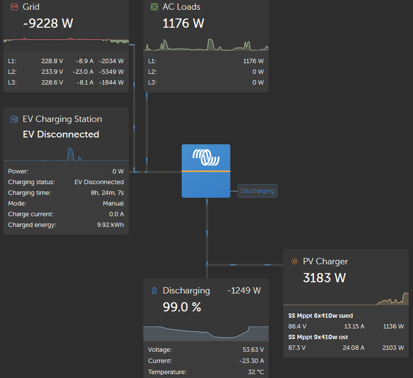
I have a Multiplus GX with two Mppts and an external AC inverter controlled by a JK BMS with Can (pb2a16s15p). All battery values appear in the remote console.

 As soon as I reach 100% Soc the BMS switches between charging and discharging every few seconds. The level of charging/discharging is also different, +-5A, +-10A, up to +-30A. If I switch off the MPPTs, the Multi only takes 1-2A from the AC inverter, but even then charging/discharging occurs around the float/charge end voltage. If I take out the float mode in the JK bms, the voltage applied to the RCV increases but there is also charging/discharging.

Why does the float/charge voltages overshoot and then have to be regulated down by discharging???

It's also strange that in the morning my battery jumps from 50% SoC to 95%-100% SoC within 30 minutes. I only charge with 65a so there's no way it's full. The voltage doesn't match 100% either, it increases from almost 52.0v to 54.0v. I have Soc in BMS on 55.2 so 100% shouldn't actually be displayed.

There is even discharging of the battery while exporting to the grid. (see picture) mpps  deliver 3.2kw, the inverter dicharges with 1.3kw all while the AC coupled inverter exports 5wk at the same time

BMS setting and VRM screenshot in which you can see the SOC jump yesterday morning from 8:00 to 8:30 (this happens pretty much every day).
asked
Multiplus jumps from charge to discharge
@acme
If you are using the side loaded driver I am sure you read the disclaimer.
Best fit a BMV into the system. You will find the stability better.
SOC jump is because the trigger for full is probably a bit off if it is being determined by the BMS itself.
BMS limits when the system feeds back are ignored. So possibly that has something to do with it as well. Have you programmed the inverters and other components accordingly as well? A slight fix light be to (in DVCC) cap your battery charged voltage down a bit.
Thank you for your answer.
A BMV is a good idea but I don't think this is the cause of the issue. The SoC is not my primary concern as the system doesn't use it for any regulation. It is all done by system voltage. The voltage reading is fine. I tried all combinations, with and without battery charge and/or voltage limiting in DVCC or even disabling DVCC. No change.
The communication between BMS and MPII gx/cerbo is working. I can change the RCV in the BMS and the MP is charging to this voltage. Also, the float mode works. I have it on 1h and after that time, the MP charges to the (lower) float voltage.
Unfortunately, as soon as this happens the voltage of the battery is higher than what the MP wants and at this moment, the MP takes this as a signal to discharge the battery until the lower voltage is reached! So as soon the battery reaches the float voltage, the MP discharges 2-3kw until the battery reaches the lower voltage!
During the absorption time (for 1h after reaching RCV) and when the battery reaches the requested float voltage (RFV) the battery will oscillate between charging and discharging around the requested voltage. After 5 to 20 seconds of charging, the voltage will rise, as soon it is above the requested voltage, it will discharge with the same amps until below the RCV.
If I have no SS MPPTs connected this happens with 100-150w but if i have MPPTs connected this might also happen with 1500w to 2000w.
Somehow the MP takes a high battery voltage as a signal to discharge and not to "wait until told there is energy demand".
Could this be caused by the option "feed in excess DC" ?
I appreciate any ideas because I am all out of them.
Hi @acme
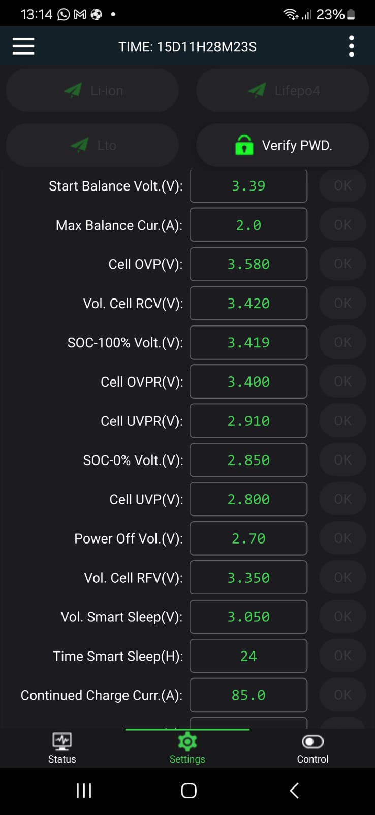
I think there are some possible improvements in parameters of your BMS
- balance voltage at 3.39 is quite high, usually better put here 3,35 which is the voltage where the trend start increasing at fast speed (meaning cell is almost full)
- you (or JK) set the voltage of 3,419 to declare SOC at 100%, this means as soon as battery voltage reach 54,72V you will declare a SOC at 100% and probably even before if this behavior apply as soon as only one cell reach that voltage. You should increase this up to 3,50V and ask JK about this logic : is the forcing to 100% of SOC linked to only one cell voltage up to this limit or is ther any other rule?
Hi, thank your for your answer.
Out of desperation, I was playing around with the values to see if it made a difference.
You are right about the balancing. I didn't want it to be too low so as not to balance in the "flat" spot. But it can be a bit lower for sure.
For SoC it calculates 16*SOC = 100% voltage. I usually have it at 3.45v and 3.44v. So it's 55.2v requested cell voltage and 55.04 Soc100. The BMS does not allow setting SOC100 below the RCV to avoid the battery never reaching 100% SOC.
Do you have any idea about the oscillating problem? (see my answer to Alexandra for a slightly better description of what is happening)