Yesterday I asked a question 'DVCC Maximum Charge Current setting - Is this expected behaviour' and found that I had stupidly mistaken DC Amps for AC Amps !! that has now been corrected and works. However another part of the problem has not been resolved.
My MPII is only connected to AC In 1 and is only being used to charge and discharge its attached batteries. Charging is enabled via ESS to take place when we have cheap rate electricity between 2330-0530 each day, discharging is being enabled manually when the Growatt batteries reach minimum allowed SoC.
The MPII not handling or switching any loads and the Victron Grid current limit is set to 20 amps (temp MCB is only 20 amps).
Following further testing I now believe that the MPII is limiting ESS charging based on the total load on the house which it sees on its CT clamp, I had assumed that the 20 Amps grid current limit would apply only to the load through the MPII rather than the house load?
Last night I changed the inverter to charge only mode and when ESS charge was active and I could see some charging but only when the total load that the MPII was seeing was below the 20 Amp Grid Limit, for most of the cheap rate period our use is well above that and averages about 6-8kw.
Thinking about this the MPII actions do make sense but It give ma a problem which I am not sure I can resolve, I could disconnect the CT from the MPII and let it use its internal sense (set jumper) but if I do that then it won't see any demand when it should be discharging its batteries. I could move the CT clamp somewhere else but I am not sure where? Are there any other options? e.g. a manually offset of the CT reading to reduce it? some other Victron settings?
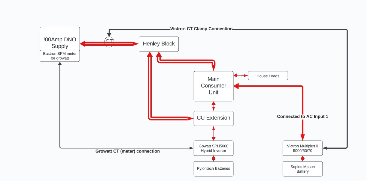
I have attached a very poor simplified diagram of my system which may help.
For background only:
- This is a temporary setup, the aim is to move to full Multiplus control but that required extensive rework of my CU to remove some high current circuits (ASHP and car charger)
- My original installer has disappeared and I am struggling to find someone with Victron knowledge to take over.
- I have G99.
- I have PV attached to the Growatt but non on the Multiplus.