I have been experiencing the following problem for a few weeks now.
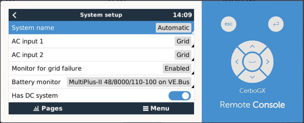
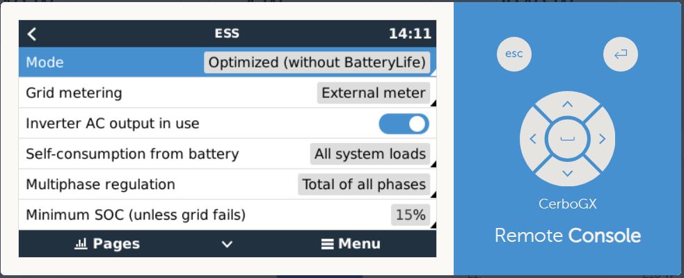
At ESS I have: Minimum charging status (unless the electricity grid fails) 15%. and Set power supply 0W
When power is required, it will first come from the batteries until they are equal to or lower than 15%.
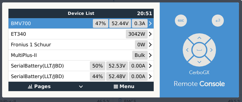
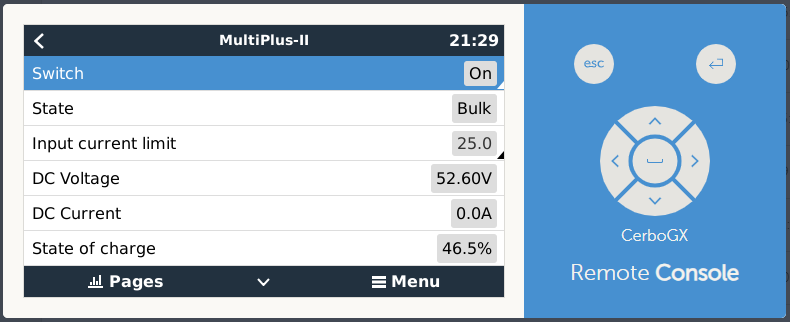
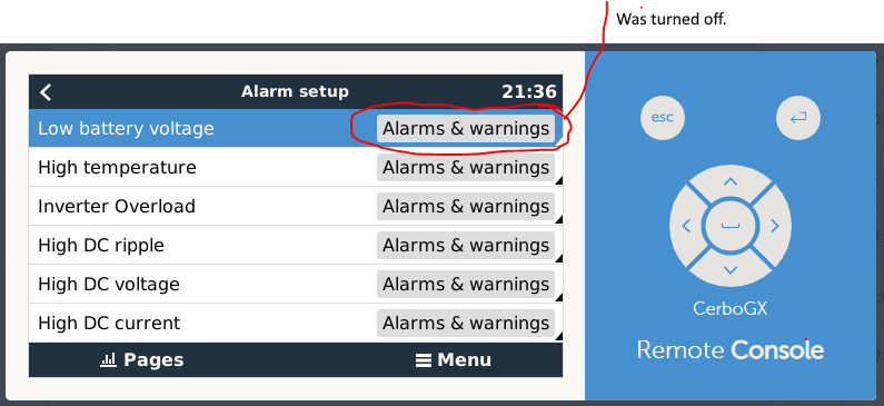
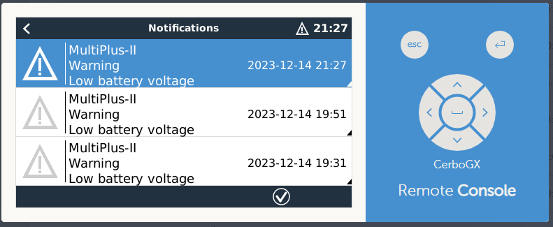
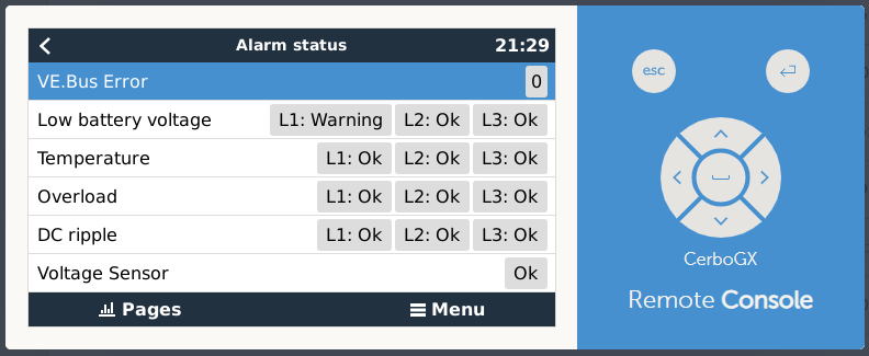
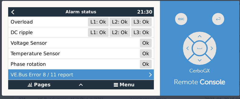
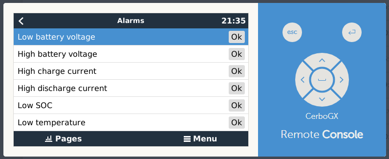
This worked well, but now the battery power keeps stopping between 45 and 50%. If there is a power failure after this, then the system breaks down! The system apparently thinks the batteries are empty?.
The system I have running is as follows:
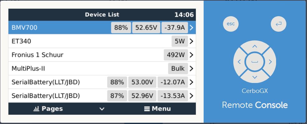
3x Victron Multiplus-II 48/8000 3 phase setup.
1x ET340 Electricity Meter (Multi-phase)
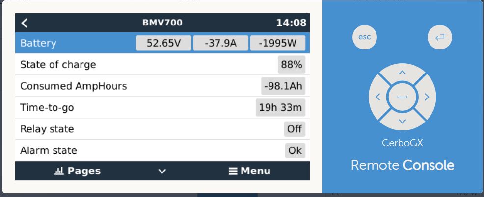
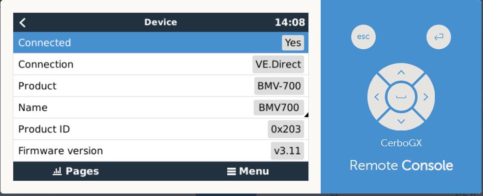
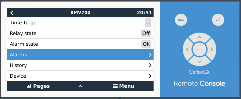
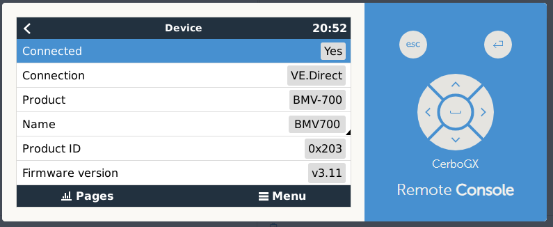
1x BMV-700
1x CerboGX
1x SmartSolar MPPT 250/70 (4000Wp)
1x Fronius Symo 6.0-3-M (Connection IP (sunspec)) On AC output
1x Aurora Power One 4.2 Inverter 1 phase on AC output. (Will be replaced in the near future by a Fronius symo)
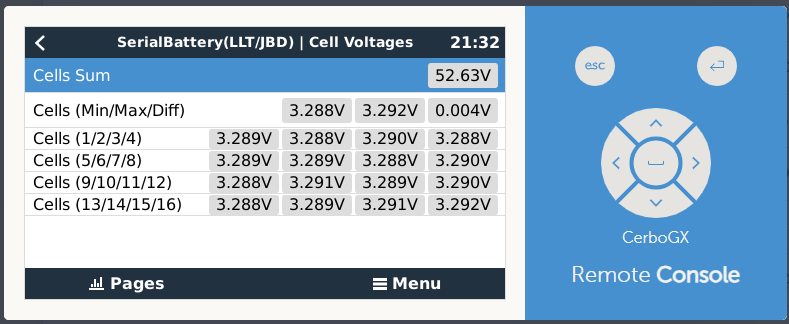
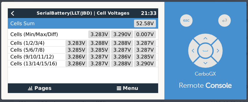
3x Overkill Solar BMS (16s 100A) with 3x USB Module for BMS. Considered as SerialBattery(LLT/JBD)
3 sets of 16 cells LifePo4 280Ah. Is 3x280Ah=840Ah total.
Firmware:
CerboGX: v3.13
Multiplus: 508
SerialBattery(LLT/JBD): 1.0.20230531
BMV-700: v3.11
SmartSolar MPPT 250/70: v3.13
Fronius: 0.3.30.0
Fronius DataManager: 3.28.1-3
The reason for 3x BMS instead of 1x is that you can now charge and discharge with 3x100A (300A) instead of 1x100A.
I got the BMS visible in Cerbo by using the Louisvdw/dbus-serialbattery driver.
This is the latest release! Installed via SSH and Root access:
wget -O /tmp/install.sh https://raw.githubusercontent.com/Louisvdw/dbus-serialbattery/master/etc/dbus-serialbattery/install.sh
bash /tmp/install.sh
Addition: When I set a planned charging level with a SOC limit of 100%, the batteries are charged with approximately a maximum of 110A. Before the problems arose, it was (depending on the charging status) around 300A.
What I have done so far to get the problem resolved:
I used Latest Release candidate for the Cerbo. But now back to the stable due to problems.
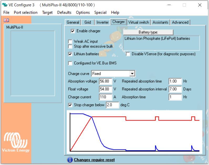
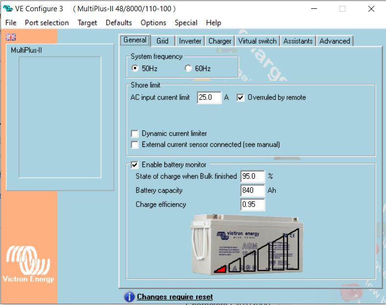
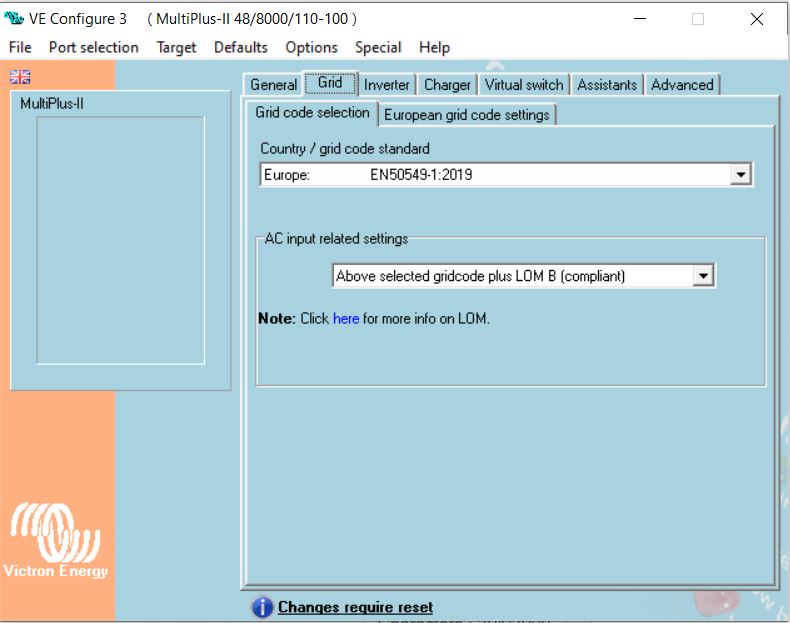
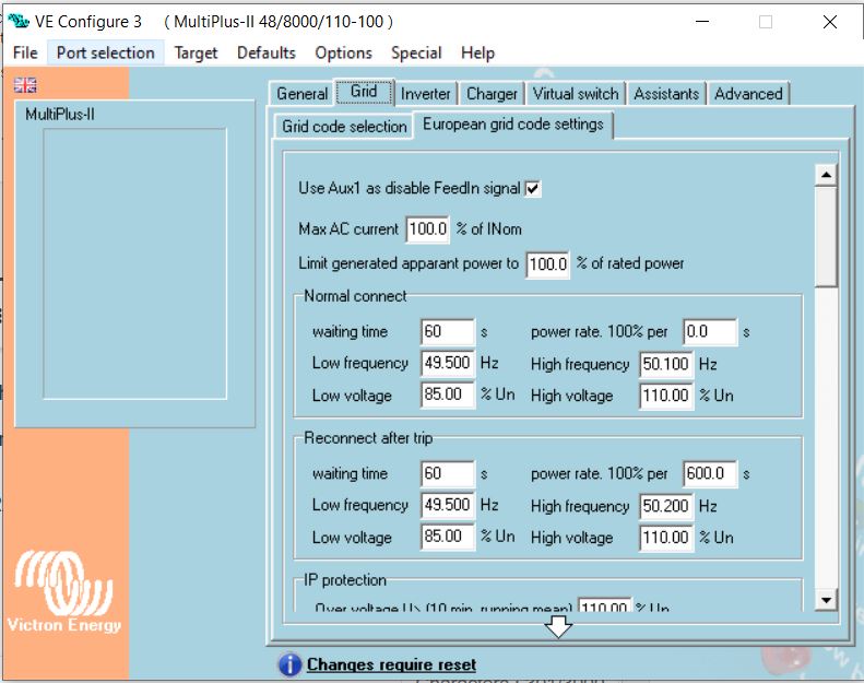
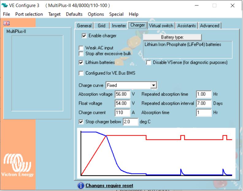
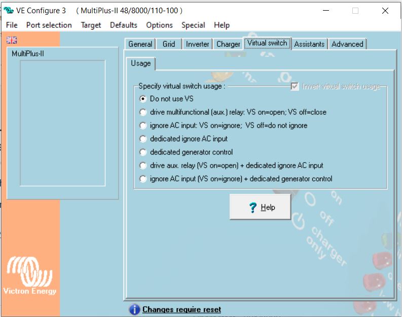
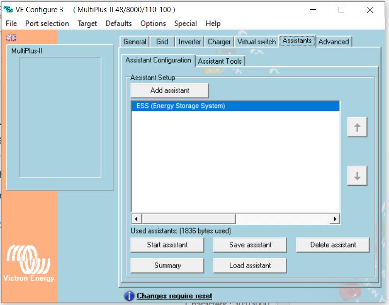
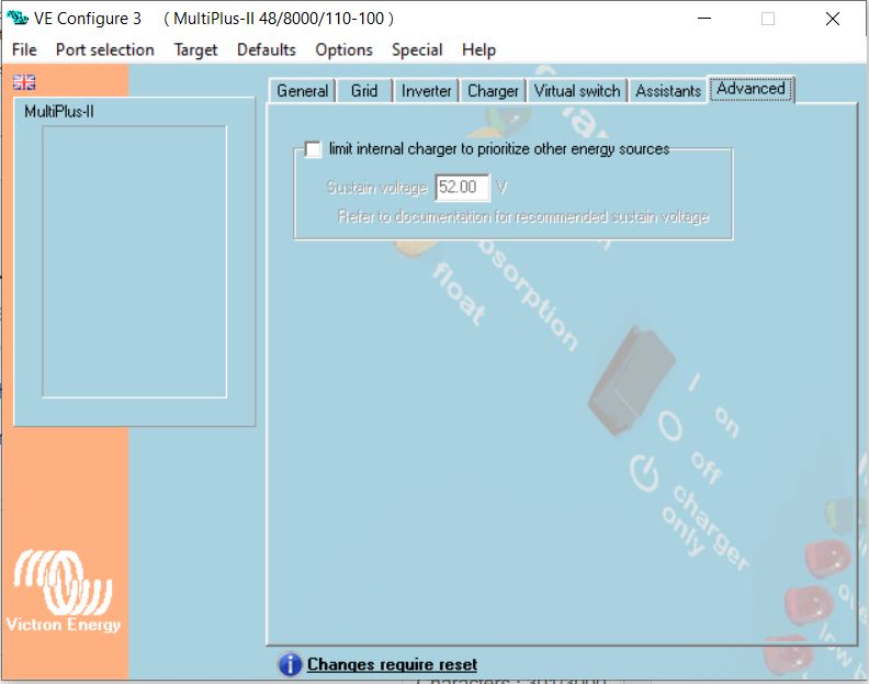
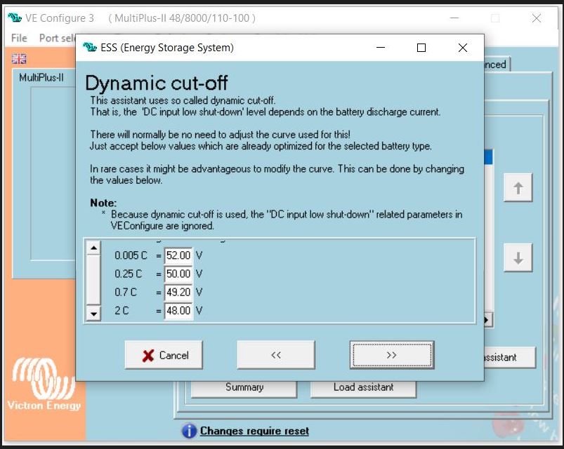
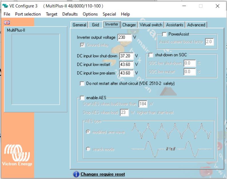
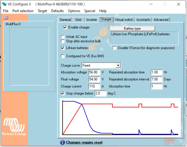
With VEConfigure3 the 3 multiplus units were reconfigured with the ESS Assistant again.
I also reset the CerboGX to factory settings using venus-data.tgz.
After this, the Cerbo was set up step by step.
Update Louisvdw/dbus-serialbattery driver to the newest (1.0.20230531) on this moment.(>= V1.0) (Not the Nightly build!)
Unfortunately everything without results.