question

sra189 avatar image
sra189 asked

Multiplus 2, charger voltage runaway on first activation -> dead batteries ( @ victron stuff ?? )

Good day,

At the beginning an apology about my English. It is not my native language therefore possibly some translation errors...

We are working with Victron Equipment around a year now. We built in summary 6 Systems with different objectives.

- All Systems were built with Multiplus II 3000 + 5000
- Location Germany
- Battery -> Pylontech US3000C for all working Systems


We never had any problems with the ESS System itsself until End of last week on the latest system we built.....


-Multiplus II 3000VA 1x as ESS installed and configured
-Pylontech US5000 2x as Battery Master configured and Connection + Data Exchange established.
-no MPPT's
-AC coupled PV Inverter integrated with EM540 on primary site ( AC-IN )
-No Critical loads

1.: Initial Situation:
The system was completed in the middle of last week and should go into regular operation in the coming weeks (depending on the energy supplier).

To let the two installed US5000 perform an appropriate cell balancing we have activated the Multiplus in the setting " keep batteries charged".
Max Load Current was configured to 2A
DVCC Max Voltage was configured to 52,2V


2.: Loading to 95%
The Activation of these settings were on Friday , 28th of july
From now on the system was loading the brand new battery stacks until 96% as we all expected and we did it in the past...


Here The loading graph over 2 days
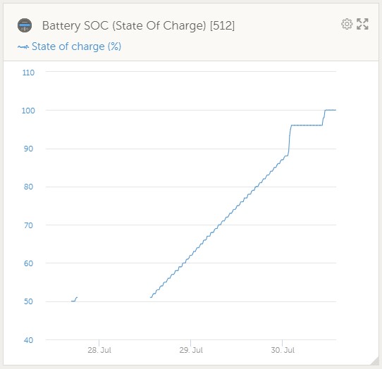
screenshot-2023-08-02-174941.jpg

1690991614511.png


2.: Loading to 100%
On Sunday the 31/07/23 around 10:30 am we increased the DVCC max level by 0,1v to reach upper level

screenshot-2023-08-02-175924-2.jpg


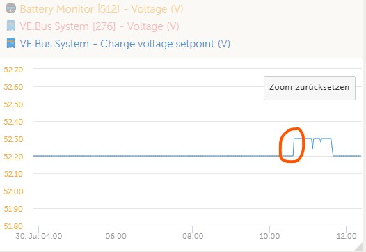
The following reaction was as we expected the increasing SOC and also decreasing CCL reported

screenshot-2023-08-02-180335.jpgscreenshot-2023-08-02-180434.jpg


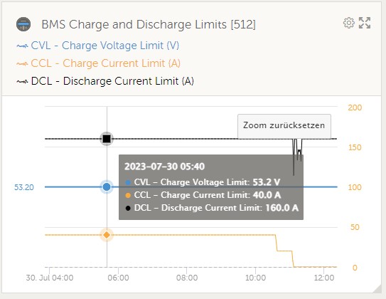
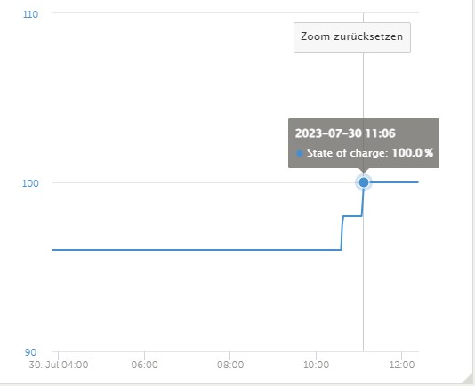
until this point the system worked within its parameters and without any problems in our opinion... The Batteries should now be on soc 100% and balancing internally for the first time


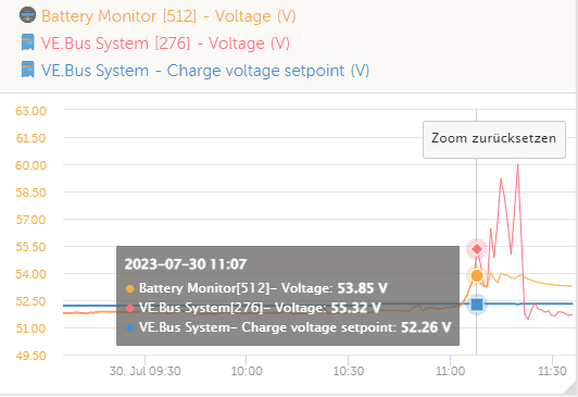
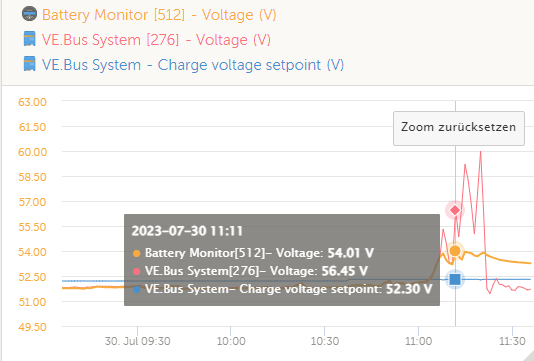
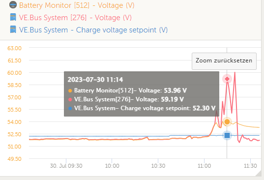
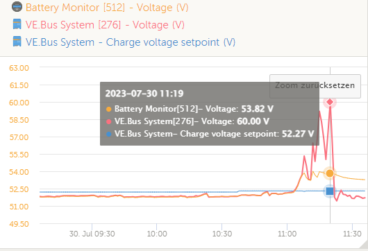
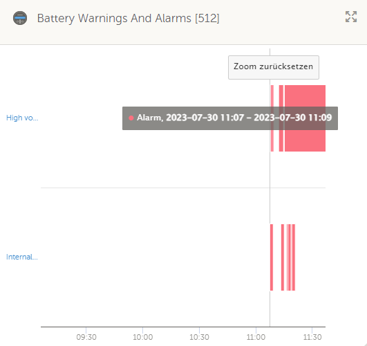
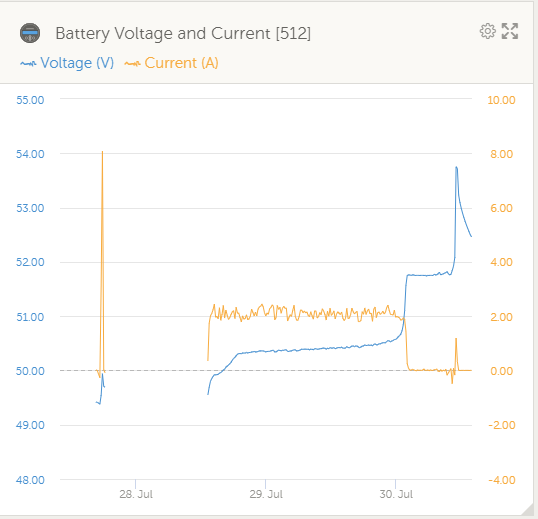
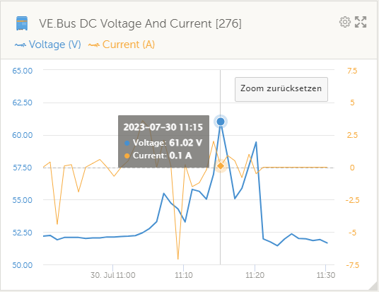
3.: Reaching 100 % -> Runaway of the multiplus DC Voltage

1690993377322.png1690993392424.png


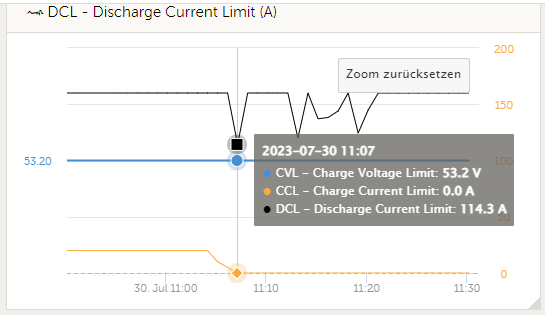
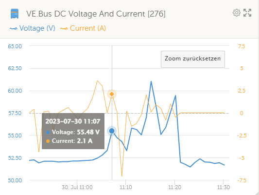
When reaching 100% SOC and the BMS retourned CCL=0 we had the first massive voltage peak reported on the dc System. we also can see this peak in the bms communication...


1690993510146.png


as an effect of this voltage spark the batteries were shutting down. we are not sure ift hey are dead now... if we activate them we have no errors on the batteries but we have no voltage on the main connectors.


The strange thing we are trying to understand..... why is the voltage increasing ... what was the trigger for doing that ? ...

and what is much more importand ... why can the multiplus increase the voltage over the configured levels of 52V/51V and also the DVCC max Voltage ?? In our opinion the spark is generated by the multiplus cause there is no other energy source on the dc side ...


As you can see in the screenshot we reached more than 61V as a max ????

1690993827216.png


We checked everything twice now... everything seems fine ... the only difference to the other systems we built successful and to the fullest satisfaction is that this system is only 1 Phase and all other systems aler 3p systems !?!?!?

What are the possibilities?
defective inverter ?
wrong Voltage measurement on the multiplus ?

we are glad to hear any food for thougt !! Currently we no longer know where to search ....


thx alex


epilogue:
BMS Communication to the pylons established without problems
VE BUS Communication MP2 / Cerbo gx established without problems
all Parameters configured for Pylontech as recommended


Multiplus-IIESS
2 |3000

Up to 8 attachments (including images) can be used with a maximum of 190.8 MiB each and 286.6 MiB total.

7 Answers
Alexandra avatar image
Alexandra answered ·

@sra189

If you have solar, the DC bus Volts and amps do not correspond to battery charge and voltage.

It is a measurement of power over the bus - it can also be direct to loads or to feedback.

Pylontec requests 53.2v from the system, that is at the battery request. It is still within the battery capabilities as well according to the datasheet. The ve bus coltage set point is how the system works the solar before pulling from the battery - an effect of ESS. Also not too high for the battery.

If there are no alarms besides the usual ones for a new system, all is well. Your batteries are charging to the correct voltages - all is as it should be.

2 |3000

Up to 8 attachments (including images) can be used with a maximum of 190.8 MiB each and 286.6 MiB total.

sra189 avatar image
sra189 answered ·

Tanks for your Response.

We know that if solar is Connected the mppt parameters for voltage are higher than the setting in dvcc 0.4v for 48v Systems. But as i described we have no mppt Connecticut.. only the multiplus as charger.....


Also we got different alarms from the pylons ( overvoltage and International failure as a result ) .. they are dead as it looks like !


As you discribed we know the problems with New Systems abd batteries the first das... because of that we now do the Initial Charge oder das with very smalltalk current...

2 |3000

Up to 8 attachments (including images) can be used with a maximum of 190.8 MiB each and 286.6 MiB total.

sra189 avatar image
sra189 answered ·

Omg... sorry for some words on the Response... it seems the autocorrection of some words does not work well

1 comment
2 |3000

Up to 8 attachments (including images) can be used with a maximum of 190.8 MiB each and 286.6 MiB total.

Alexandra avatar image Alexandra ♦ commented ·

@sra189

Not a problem. It happens. I am always editing my posts for spellings and things like that.

I saw no mppts but you call it an ESS system.

Do you have ESS assistant installed? Even though you have no mppts?

Even if not, the ve bus voltage and current are completely unrelated to the battery voltage when they are processing loads.

As you have seen your battery voltage does not rise to the 67v.

1 Like 1 ·
sra189 avatar image
sra189 answered ·

Yes the ess assistant installed... maybe i descrbed it not exactly... an existing pv inverter is connected ac but only on ac in .. no Connecticut on ac out or ac out2

2 |3000

Up to 8 attachments (including images) can be used with a maximum of 190.8 MiB each and 286.6 MiB total.

sra189 avatar image
sra189 answered ·

in addition to my question some further informations...

1691053215106.png


This is the system configuration with the existing problem...


Also we have thought intensively about potential differences between the systems we already installed successfully:

1 - All other Systems are on FW 501 ... This system is the only one with FW502 ...
2 - The other systems are configured as 3p systems not as 1p
3 - All Other Projects so far was realised with US3000C


1691053215106.png (143.6 KiB)
2 |3000

Up to 8 attachments (including images) can be used with a maximum of 190.8 MiB each and 286.6 MiB total.

sra189 avatar image
sra189 answered ·

besides the reaction of the palontech batteries after the voltage spike


overvoltage alarm -> internal error -> failure of the two US5000 batteries

1691053801324.png1691053821732.png1691053835275.png1691053845584.png

1691053927346.png


with up to 60V the batteries were grilled

The question remains :
HOW CAN IT BE THAT THE MULTIPLUS INCREASES ITS VOLTAGE SO DRASTICALLY ?
PROBLEM IN MULTIPLUS FW OR VOLTAGE MEASUREMENT ??


1691053801324.png (36.9 KiB)
1691053821732.png (38.0 KiB)
1691053835275.png (39.0 KiB)
1691053845584.png (38.6 KiB)
1691053927346.png (15.0 KiB)
5 comments
2 |3000

Up to 8 attachments (including images) can be used with a maximum of 190.8 MiB each and 286.6 MiB total.

Matthias Lange - DE avatar image Matthias Lange - DE ♦ commented ·

Normally the BMS should shut down the battery in case of a high voltage to prevent any damage.

The graph shows around 60V from the VE.Bus system but "only" 53.8V from the battery monitor (the Pylontech battery) so the high voltage shouldn't have reached the battery.

Have you disconnected the batteries and tried to start them individually?


"load" ist nicht laden im Sinne von (einen Akku) Aufladen, sondern die Last, also das genaue Gegenteil.

Das Aufladen eines Akkus ist "charge" bzw "charging"

1 Like 1 ·
sra189 avatar image sra189 Matthias Lange - DE ♦ commented ·

Hi Mathias,


I was expecting the same as you mentioned.. the BMS should have prevent damages...


Of course we disconnected both US5000 and measured the connectors. Both batteries have no voltage on the outputs.

The interesting thing is that there no errors on the Batteries itsself. They are starting normally and going to idle

readout of the bms (history and alarm logs via battery view ) resulted in the following:

Errors of high voltage vor single cells ( more than 3.65 ) and also Errors of high voltage for the pack ( >54V ) are logged. BMS shutdown is logged also.


at this point an shutdown of the connection to the internal structure was exprected from us. after coming back to " normal" state of the cells ... <3.5 V as OV release voltage and also the general pack < 52 ( all these values are configured in the BMS ) we expected an restart of the charge and discharge mosfets.

The state of these are activated when we made a readout with batteryview, but there is neither voltage on the connectors side.

both batteries show normal run without any errors as i described.

we have tried all combinations now.. standalone, connection between batteries, connection to the victron system ( no errors, all parameters within their expected values ) .


Our conclusion for the pylontechs is that they are damaged permanently. As we have seen there are some posts about internal fuses for overvoltage of the packs ... maybe thay are blown !? unfortuntely there is only very view information available of the BMS and its structure. thats a hard fact but well ... it is what it is :-(


0 Likes 0 ·
sra189 avatar image sra189 Matthias Lange - DE ♦ commented ·

The Main Problem for now is :

I think we understand what happened on the pylontech side and the resulting damage.

But what was the trigger on the victron side ?? we are not willing to connect the next pack and get the same result ...

We always used at least the recommended manufacturs, configurations and also capacities which are tested and supported from Victron for preventing us and our clients for such situations.


So we really DONT UNDERSTAND how the voltage on an multiplus ( standalone in charging as i described above ) can exceed the configured limits of voltage ?????

I Think that we have to clarify finally before we can go the next steps.


All components were brand new and out of the packaging... so maybe the multiplus has an error ?????? or the firmware ??


To the vrm data collection and the values we can see there... We are not really shure how the data collection is generated in the cerbo here ( trigger on time, trigger on deviation to last level, .... ) As i see the data points on vrm has a limit of the resolution ( 1 minute i asume ). Thats completely ok for normal things and we are all satisfied about the possibilities we habe in this system.

But i think in our concrete situation we would need a high resulution in a very small time frame ... My personal thinking here is... we dont see the exact situation in vrm !?


OMG... what a reply... thank you for reading until here ! :-)

0 Likes 0 ·
Alexandra avatar image Alexandra ♦ commented ·
The problem is likely coming from the AC coupled PV. Over production overshoot or something like that.

Possibly there is a large load, pv is covering it, it drops off - pv energy takes a few seconds to resond but the energy is there.

VE bus voltage is rising when there is alot of energy and there is nowhere for it to go. The batteries are shutting down because they cannot sink the overproduction.

So start by looking at the AC PV.

Cap the voltage in DVCC to around 52v.

Your other option is to roll back to v501. If you really think that is the issue. Did you update firmware on the EM?
0 Likes 0 ·
ardes avatar image ardes Alexandra ♦ commented ·

The way the system is shown in sra189s picture above, wouldn't excess energy from the existing AC coupled PV be fed back to the grid?

0 Likes 0 ·
sra189 avatar image
sra189 answered ·

I would agree all what you are explaing if the pv inverter would be connected on out1 of the multiplus. But here the pv inverter is only connected via et340 for registration the energy and to have summaries on vrm

also no spike on the pv inverter on related time ...
the yield was falling not rising ?

1691061451463.png


and i am a little bit confused about your other thinking ... Multiplus was only a charger in this time ... so the charger must be able to control its charger voltage ... am i wrong ?

"Cap the voltage in DVCC to around 52v"

as i wrote... they were at 52.2V/52.3V ... also internally would be at highest 52.4v because identified as pylontech and no dc feed in ...
In addition all parameters in multiplus are configured right ( 52v/51v, assistant, .... )


"Your other option is to roll back to v501. If you really think that is the issue. "
actually it is no option for us to change the firmware at the moment cause we want to identify what happened .... it is no option to connect another pylontech set an maybe the same will occur if the problem is not identified before

"Did you update firmware on the EM?"
No update on em540 before.... its the rs485 version ... not the Modbus tcp


1691061451463.png (18.7 KiB)
2 |3000

Up to 8 attachments (including images) can be used with a maximum of 190.8 MiB each and 286.6 MiB total.