question

daza avatar image
daza asked

System design. In Buckinghamshire

Hi everyone

im struggling with system design and what I need. ideally I would like everything to run off of backup batteries as well But my system is split already.


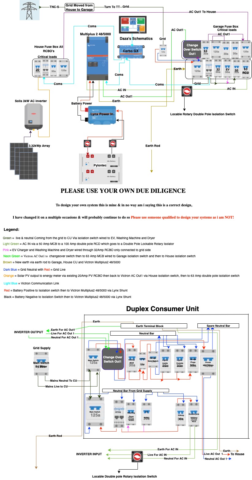
So I have a Henley block from the main income splits the garage consumer unit and the Houses consumer unit. I have a 3.3kW array, solis ac coupled inverter to the houses consumer unit. The Batteries and Victron Inverter would be installed in the Garage.


ideally I would like the solar, loft kitchen and the garage sockets to operate in a grid down manner still ie so I would have to split out the house consumer unit or run the mains to the garage and take it back to the house from the inverter but also have provisions to switch back to grid in the event of inverter replacement.


I looked at the 48/8000 Multiplus which is capable of 100Amp switch so would run the house without overloading, the 48/5000 is another option but would see me having another consumer unit in the garage and another in the house inorder to split the garage sockets , and in the house the loft, kitchen and solar.


I am aware I’ll need to run SWA cable depending on the options of inverter. I’m capable of running two 25mm SWA cables to satisfy 100Amp draw. I could run Cat5e Cable to the garage for the ESS but I have no idea how many pairs I would need to run to the cerbo GX so that I could monitor the solar as well as the incoming from the grid. Also how many Pylontec batteries would I need for each Multiplus 2?


Any help with design would be appreciated and PS is there Victon installers in Buckinghamshire?

system design
2 |3000

Up to 8 attachments (including images) can be used with a maximum of 190.8 MiB each and 286.6 MiB total.

19 Answers
sharpener avatar image
sharpener answered ·

Hi, two last comments.

You haven't shown the data connections from the meters to the Cerbo.

Changeover switch connections are still a bit unclear as the RCBOs aren't labelled. Presumably the intention is to feed the Critical Loads panel from the switch and have the alternative inputs from the AC-Out or from the grid via suitable EL and overload protection somewhere. The Multi AC-In should have its own RCBO separate from the grid feed to the switch.

ATB

1 comment
2 |3000

Up to 8 attachments (including images) can be used with a maximum of 190.8 MiB each and 286.6 MiB total.

daza avatar image daza commented ·
Yes I plan to fire off an RCBO from the grid in the duplex in the bottom part of the CU it’s all going to be done from the inside the duplex told the spark it would be a 20+20 he was shocked, I’ve just got to work out if the wall is big enough for inverter and the CU, as I would rather have too much room in the CU to route and keep cables tidy.


Yes changeover switch feeds the critical loads I will need to do a logic circuit with the switch linking two together with one bar as Hager ones can’t take the full 100amp that I could have coming through the grid, logic by name as it would just be swtches operating as one to achieve disconnection from AC Out1 from the grid, trying to keep Hager but they don’t do a 100 amp or higher change over switch. Was trying to stick with them but might need to ditch just don’t want to loss 8 RCBO’s that are al in the garage CU


I didn’t bother doing the communication links to the ET112 as I thought it would be self explanatory but yes noted, from the house I’m coming out to the garage CAT5e armoured then terminating to Victron spec as I know they don’t do A/B system with the CAT cable.


0 Likes 0 ·
sharpener avatar image
sharpener answered ·

The ET112 in the house CU is needed so that the solar generation will show up correctly in the Remote Console as a separate tile called PV Inverter.

If you do not have this, the system will work OK and not export un-necessarily, but the PV will be treated as a negative AC load and so the AC Loads on the RC will under-read by the amount of the PV. If it exceeds the actual loads they will read zero not the correct (negative) amount.

If you have other ways of measuring what is going on then of course you may not care about any of this.

2 |3000

Up to 8 attachments (including images) can be used with a maximum of 190.8 MiB each and 286.6 MiB total.

sharpener avatar image
sharpener answered ·

@Daza your approach to date sounds fine, the main considerations have all been addressed.

But you don't say how far away the garage is, which may be significant.

TLC catalogue rates 16mm^2 SWA at 110A so 25 is probably overkill. Maybe a wireless repeater would be easier than cabling for the Ethernet, I have 2 x TP-Links elsewhere in my system (and a Harvi for the Zappi charger). If you are burying it either allow spare ways or lay a duct, I wish I had done this when the drains were up.You can get combined Cat 5 and power SWA but it is expensive.

The 8kW Multi would need a bigger minimum size of battery which will up the cost even more. I have the 5kW Multi and 10.5 kWh of Pylons which are fine for a biggish house, everything is connected to the AC-Out incl. 16A of solar and the electric cooker, so you might not even need to split the loads as you propose unless you have e.g. electric shower or space heating to contend with.

The whole ESS is wired in 10mm^2 from a 50A breaker which has never yet tripped. There are separate changeover switches (as you are also proposing) to bypass the inverter, I only use the garage one, when I need to charge the car overnight from the grid.

However AFAIUI the UK approval for the 5kW model is still pending, yet again.

Good luck, no doubt the regular posters here will have lots to add.


2 comments
2 |3000

Up to 8 attachments (including images) can be used with a maximum of 190.8 MiB each and 286.6 MiB total.

daza avatar image daza commented ·

@sharpener
Wow thanks for the points I assumed it had to be 25mm. the run to the garage is no more than 15metres to be on the safe side of bends and positioning, the highest load I have would be the electric oven, microwave and maybe the airfryer. I looked at the Doncaster Electric vehicle cable combined with data max size is 16mm.


So as for change over stuff that would all have to go in the garage glad you mentioned EV, I haven’t got one but would like to factor that in, but maybe I can do this as a separate board in the garage that is only connected to the mains going into the Victron so outside of the inverter so not passing through it but around it?


My main fuse box is nearly maxed out as I’ve only got 3ways left from an 18way board, everything in the house is on a radial with separate zones as I have an extension only ring in the house is the kitchen and a ring in the garage for washing machine and dryer but I can separate that in another board or just put it on the AC side like the EV would be?


I don’t mind running data cable as I would have to run the mains cable for the inverter out to the Garage. I assume if I had the EV connected to the garage I would want 25mm cable from the mains. I know it would be overkill but if I was laying it I may as well over engineer.

My Garage board has some spare ways, but from the sounds of it I can do a breakaway board just before the inverter to house the ESS and also the EV and easing machine and tumbler, then I wouldn’t ever reach inverter overload and the inverter would still see all the loads on the system to allow the battery and solar to provide the power.


Ive been looking for changer boards but I can’t find anything, how many Pylontec batteries would I need for the 48/5000 multiplus 2 inverter?


Thank you very much for your help sounds like you just saved me a lot of coin well when I get round to start buying bits. Yeah money and the awaiting approval is one of the reasons why I haven’t done anything yet as it’s still all up in the air as I don’t want to invest if I can’t even turn it on.

0 Likes 0 ·
sharpener avatar image sharpener daza commented ·

<Ive been looking for changer boards but I can’t find anything>

not sure what you mean. Be aware that requirements for EV chargers are a can of worms e.g. like an ESS they may not share an RCD with other loads. So if the EV cct is split off in the garage then you should supply the gge sub-main from a DP switchfuse not an RCD, then have individual DP RCBOs in the gge itself. Also unless you have 3 phase you will be limited to 7kW for the EV anyway so not a massive load.

<how many Pylontec batteries would I need for the 48/5000 multiplus 2 inverter?>

Well I started with 2 modules (7.1 kWh) and technically it worked fine (despite what many posters said on here). But in summer, cooking the evening meal exhausted it before the cheap rate came on (in winter we have an AGA).

So I increased it to 10.5 when I added more PV panels on the DC side and now it rarely runs out. When we are away it lasts for 2 days without any sun so grid consumption is essentially zero.

Good thinking about putting the washer and dryer on the AC-In side, as you say with the current sensor in the right place the inverter can still feed them except in a power cut. So you will also need to run the sensor cable from the garage back to the intake in the house.

I would suggest your next step is to draw a single line diagram of your whole system, as you will need this anyway to get installation quotes. There are some good examples on here e.g. by @Jason - UK which you can start from, then post it back here and ppl will be all over it. After that you will know so much about the Victron ESS side (!) it will just be a job for your usual electrician.

If you buy from someone like @ejrossouw rather than one of the sheds you will get a lot of pre- and post-sales support too.

2 Likes 2 ·
daza avatar image
daza answered ·

@sharpener Wow thanks for the points I assumed it had to be 25mm. the run to the garage is no more than 15metres to be on the safe side of bends and positioning, the highest load I have would be the electric oven, microwave and maybe the airfryer. I looked at the Doncaster Electric vehicle cable combined with data max size is 16mm.


So as for change over stuff that would all have to go in the garage glad you mentioned EV, I haven’t got one but would like to factor that in, but maybe I can do this as a separate board in the garage that is only connected to the mains going into the Victron so outside of the inverter so not passing through it but around it?


My main fuse box is nearly maxed out as I’ve only got 3ways left from an 18way board, everything in the house is on a radial with separate zones as I have an extension only ring in the house is the kitchen and a ring in the garage for washing machine and dryer but I can separate that in another board or just put it on the AC side like the EV would be?


I don’t mind running data cable as I would have to run the mains cable for the inverter out to the Garage. I assume if I had the EV connected to the garage I would want 25mm cable from the mains. I know it would be overkill but if I was laying it I may as well over engineer.

My Garage board has some spare ways, but from the sounds of it I can do a breakaway board just before the inverter to house the ESS and also the EV and easing machine and tumbler, then I wouldn’t ever reach inverter overload and the inverter would still see all the loads on the system to allow the battery and solar to provide the power.


Ive been looking for changer boards but I can’t find anything, how many Pylontec batteries would I need for the 48/5000 multiplus 2 inverter?


Thank you very much for your help sounds like you just saved me a lot of coin well when I get round to start buying bits. Yeah money and the awaiting approval is one of the reasons why I haven’t done anything yet as it’s still all up in the air as I don’t want to invest if I can’t even turn it on

2 |3000

Up to 8 attachments (including images) can be used with a maximum of 190.8 MiB each and 286.6 MiB total.

daza avatar image
daza answered ·

@sharpener
Right so think it goes like this please be gentle. I'm pretty sure I've got every victron device i need in the schematics, for the victron to run and also do my critical loads which would be the whole house and Garage with the exception of the Washing Machine Tumble dryer and EV charger running off of the Grid and supplemented by battery when the grid is still running. The wiring is single Phase.


I know i could run this out of the none critical loads of the Victon but if i get an EV with that and Washing Machine and Dryer its a heavy load plus it would be a pain wiring it all up in the event the inverter went to wire AC out 1 and AC Out 2 in as well as AC In 1 together to get power back to the house that's why I'm not using AC Out 2. Instead the grid feeds to a main board and to the EV,Washing Machine,Dryer and inverter that way i only require a change over switch and an isolation switch to safely remove the inverter should it fail or to switch over to the grid. The inverter and batteries as well as the breakout board is all located in the garage.


DESIGN edit image removed

2 |3000

Up to 8 attachments (including images) can be used with a maximum of 190.8 MiB each and 286.6 MiB total.

sharpener avatar image
sharpener answered ·

@Daza you seem to have amended the changeover switch detail since yesterday, but a still better way to do it is to have the common terminals going to the Henley block and the alternative inputs from the grid or the AC-Out1. You can get a 4-module DIN rail c/o switch which will go in yr breakout CU.

Feed the AC-In permanently from a DP 50A RCBO, that will meet the IET requirement for a two-pole isolator (though many ppl use a rotary isolator plus an mcb). With this off and the c/o set to Grid the inveter is then completely isolated for maintenance.

Metering: (i) you will need an ET112 on the feed from the Solis inverter to get the display correct though it will work without it. (ii) If you do not want to power the EV from the batteries you need that connection to be nearer the grid than the AC-In sensor, so ideally use a split board as yr breakout unit and put the CT on the link between the two halves, it is cheaper and more responsive than a second ET112.

It seems AIUI yr grid supply is to the garage not the house. You show an earth rod, be sure you are familiar with the IET island mode earthing requirements here even if you do not get hold of their entire Code of Practice.

I have got the Multi II GX model and no Cerbo: it is a bit more compact and the two-line display is quite sufficient as most of the control is done over the LAN. I am not sure if there would be a spare input for the signal from the Lynx, but then I have not got one of them either.


2 |3000

Up to 8 attachments (including images) can be used with a maximum of 190.8 MiB each and 286.6 MiB total.

daza avatar image
daza answered ·

@sharpener


Hi thanks,

Yeah I was looking over it and something wasn’t right. Not sure what you mean with the henley block wiring. But yes I would have the isolation switch from the main which is in the house then that runs out to the garage and hits the breakout board which would be the first load that the grid would see, this run in 25mm so no issues on amp draw and then fire it back to the house with 25mm so overall it would satisfy 100Amp load no issues.


The earth Rod for the victron as in island mode it would have no earth. I wouldn’t be installing the rod myself all I know it needs one when in island mode to energise the coil of the RCBO’s to trip in a fault situation.

As for the EV I dont mind some battery usage but could always manually switch over if needed, when I looked I thought a G99 requirement was for a ET112 on the grid side of the CU. Split load board they look nice but massive. But maybe I could get rid of my garage Hager and get a split load there instead? But just trying to work out wire run in my head with that option.

As for the Cerbo GX unit yeah it can plug straight into the lynx Shunt according to there manuals the whole system would be hardwired lan, that’s the way!

2 |3000

Up to 8 attachments (including images) can be used with a maximum of 190.8 MiB each and 286.6 MiB total.

daza avatar image
daza answered ·

@sharpener

Not sure if this is what you mean but yeah i could use a duplex board and separate it. Just getting a Spark to check over the regs As link you posted about the earth rod doesn’t link to anything. I figured with the earth separate it would create an imbalance when the grid goes down and trip the RCBO’s

Schematics removed as was not correct

2 |3000

Up to 8 attachments (including images) can be used with a maximum of 190.8 MiB each and 286.6 MiB total.

sharpener avatar image
sharpener answered ·

Yes, something like that.

Not sure where your metering is to achieve no export/no import. You might want to have it so the washer and dryer are on the inverter side of the current measurement, it is useful when there is intermittent sun so the battery can smooth out the supply/demand without using the grid at peak daytime rates.

2 |3000

Up to 8 attachments (including images) can be used with a maximum of 190.8 MiB each and 286.6 MiB total.

daza avatar image
daza answered ·

@sharpener

The meter is is the first connection after the main switch in the so everything would have to go back through it to get to the grid. So would it not see the draw from the grid meter and give more juice I thought that was the reason for the meter at the first point of the install?

so I’ve kind of got an idea and a build but need to talk through with a spark to see if I’m missing anything else safety wise

2 |3000

Up to 8 attachments (including images) can be used with a maximum of 190.8 MiB each and 286.6 MiB total.

daza avatar image
daza answered ·

@sharpener

I'm Finally there now, Done more research and i imagine this was what you meant? As for the Tumble dryer washing machine an EV charger they will be off of the grid but AC In will see this from the ET112 on grid side so it will see what the grid is giving and what is going back as it AC so bi directional as long as the grid is up, so the inverter should adjust accoudingly as it is monitoring grid side as well. Thats the theory anyway lol


Revision Edit of Schematics

2 |3000

Up to 8 attachments (including images) can be used with a maximum of 190.8 MiB each and 286.6 MiB total.

daza avatar image
daza answered ·

@sharpener

Thanks for some pointers i think this will be my finished system design, but showed it to a spark and he was like that system is busy so I've done some tidying and legend, so hopefully my last changes to my system design.


EDIT:

Design changed detail added hence deletion of schematics

2 |3000

Up to 8 attachments (including images) can be used with a maximum of 190.8 MiB each and 286.6 MiB total.

sharpener avatar image
sharpener answered ·

My previous post seems to have disappeared! Two last points:

  • For completeness you should perhaps show the data connections from the meters to the Cerbo

  • I think the wiring of the changeover switch is still a little unclear. Presumably the output goes to the Critical Loads board, and the inputs are (i) the AC-Out1 and (ii) a grid connection. This last should come via a breaker that is separate from the one that feeds the Multi to avoid a single-point failure mode.
2 |3000

Up to 8 attachments (including images) can be used with a maximum of 190.8 MiB each and 286.6 MiB total.

daza avatar image
daza answered ·

@sharpener


i have no idea what happened to the reply’s,

But now I’m thinking to just have the EV on AC Out2 via a changeover switch and having everything else off of the critical loads AC out1 that way I can make use of power assistance as you suggested before, it makes a lot of sense.

As far as I understand and it‘s very limited the whole system can’t use more than 100Amps so 50amps per output so the EV on its own there is fine or do you think it’s better to have it on the AC side before the inverter.

As for AC Output1 it has power assistance when coupled with batteries the breaker is to be increased from 50Amps by using their equation 5000Kv % 230V which equals 21.7Amps coupled together with power assistance gives a total max current that AC Output1 can generate with batteries is 70 odd amps.

Have I missed interpreted this somehow? I definitely need the duplex CU and all double pole isolators on all connections to the Victron. Got two sparks coming out Saturday so we can go over the cable layout and seeing if the wall can house everything.

ill use one CAT5e Swa cable to connect the houses ET112 and looks like I’ll only need to run one 25mm SWA cable to move the supply and get it back to the house via a 25mm 5core Swa. I’ll update all the coms stuff.

2 |3000

Up to 8 attachments (including images) can be used with a maximum of 190.8 MiB each and 286.6 MiB total.

sharpener avatar image
sharpener answered ·

There was a discussion on this forum in the last few weeks as to whether Power Assist will work with ESS in the way you describe, I suggest you try and find it to check what the conclusion was.

But 50A has turned out IME to be quite sufficient for the whole house (except for EV charging) and the 50A breaker has not ever tripped.

My previous reply has been moved up the thread because you "accepted" it, that is what happens but I find it quite confusing, as are the differences between "replies" and "comments".

2 |3000

Up to 8 attachments (including images) can be used with a maximum of 190.8 MiB each and 286.6 MiB total.

daza avatar image
daza answered ·

@sharpener

Thanks for your help you have allowed me to bounce some ideas off of you along with your experience having a system already. Ive added a lot more detail to the Schematics for the sparks to better understand.

EDIT: Schematics Updated

I've finally got around to breaking down the CU to see how its gonna be configured as the sparks suggested i did as it would be easier for them to plan, I've gone back to wiring the Washer and Dryer on the grid side after the ET112 so it should see the current draw and boost anyway so i should shave some off of them too if the solar hasn't got enough that's my theory anyway lol.

EV connected to the grid too. Ive had to chuck a few MCB's in there to get the desired amps. I was looking to get 70Amps on the output side of the inverter. which i could have as one of the sparks said Schneider do one but at £200 odd i'll give that a miss and settle for 63Amps on an MCB hence the double pole isolator needed to kill the garage supply.

Yes i have probably made the CU more complex than it needed to be with four double pole isolation switches, As i wanted isolation at every point without killing the whole system with one switch. i wanted to be able to shut the garage down independently of the of the house and vice versa, Boy is that printer going to be working overtime to label all of this up. Ignore some of the wires going in the wrong way in the isolation switches it was just easier to show the flow without the wires going all over the place.


Schematics edited


2 |3000

Up to 8 attachments (including images) can be used with a maximum of 190.8 MiB each and 286.6 MiB total.

sharpener avatar image
sharpener answered ·

As stated upthread somewhere IIRC, to be compliant you need a 30mA RCD to feed the inverter. However if it is two pole and lockable you don't then need the isolator after it. But many installers would for the £30 put a rotary isolator right next to the inverter, as its function is then very obvious in an emergency.

2 |3000

Up to 8 attachments (including images) can be used with a maximum of 190.8 MiB each and 286.6 MiB total.

daza avatar image
daza answered ·

@sharpener

Yes the rotary would be an in your face turn this to isolate so pretty plan as day as you mentioned, got a Double pole 63Amp hager RCD begging to be used lol. Ive looked and i can't see any lockable hager isolation switches, so rotary it is and they are really cheap thanks. i would love for RCBO's to get some higher amperage would have saved me from getting MCB's. Thank you once again for you invaluable help


DISCLAIMER ANYONE LOOKING AT THIS PLEASE DO YOUR OWN RESEARCH THIS HAS CHANGED MULTIPLE TIMES. I AM NOT QUALIFIED IN ANYWAY TO DESIGN A SYSTEM AND THIS SHOULD NOT BE TAKEN AS A QUALIFIED SYSTEM DESIGN TO IMPLEMENT IN YOUR INSTALL OR ANYONES!

gold-master-version-multiplus-48-5000-schematics.jpg


2 |3000

Up to 8 attachments (including images) can be used with a maximum of 190.8 MiB each and 286.6 MiB total.

daza avatar image
daza answered ·

@sharpener can i do away with the ET112 on the solar side and still have the system utilise the solar power and not send it back to grid if the batteries or house demands it. PS ive got a shelly with two CT's monitoring the grid and solar and ive also got a data logger for my solis not sure i need something else to tell me how much i produce or export

2 |3000

Up to 8 attachments (including images) can be used with a maximum of 190.8 MiB each and 286.6 MiB total.

Related Resources

Additional resources still need to be added for this topic