question

shannon-lowke avatar image
shannon-lowke asked

My batteries are not using their full capacity. Efficiency losses too great.

Hi Team,

We have 3x Multiplus 5000 inverters on a 3 phase system with 2x 450/100 Smartsolar MPPT and Cerbo controller. Smart shunt connected as well.

9.7kw of PV panels.

We have 8x 1.75kwh Zenaji batteries which totals 14kWh.

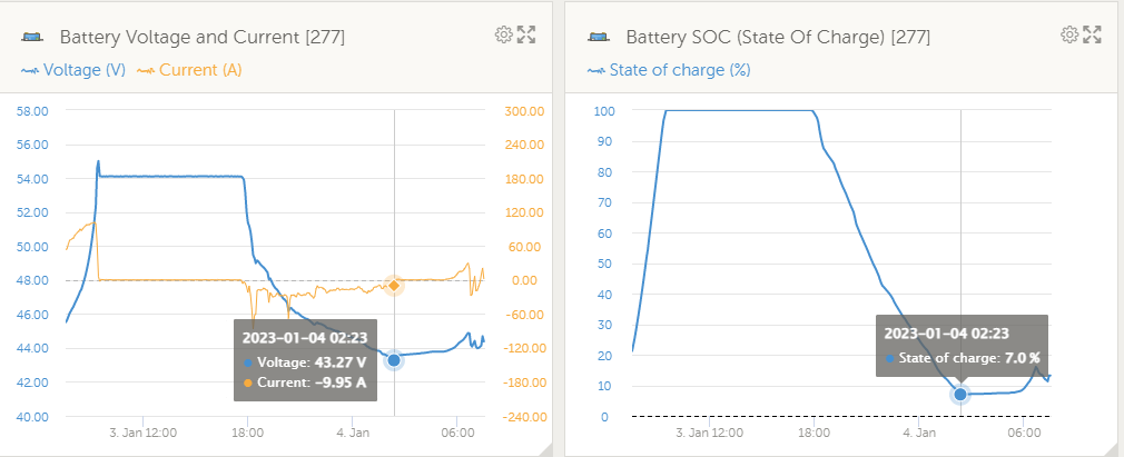
This system is technically wired as off-grid however we have the grid set up as the generator back-up. So grid comes in when batteries are depleted via generator settings. This is set as voltage and not SOC. But its basically 10% SOC cut out for the Zenaji' batteries.


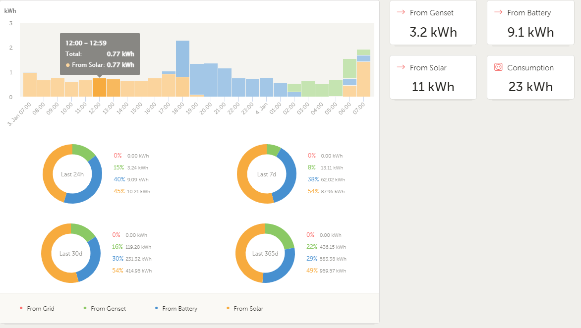
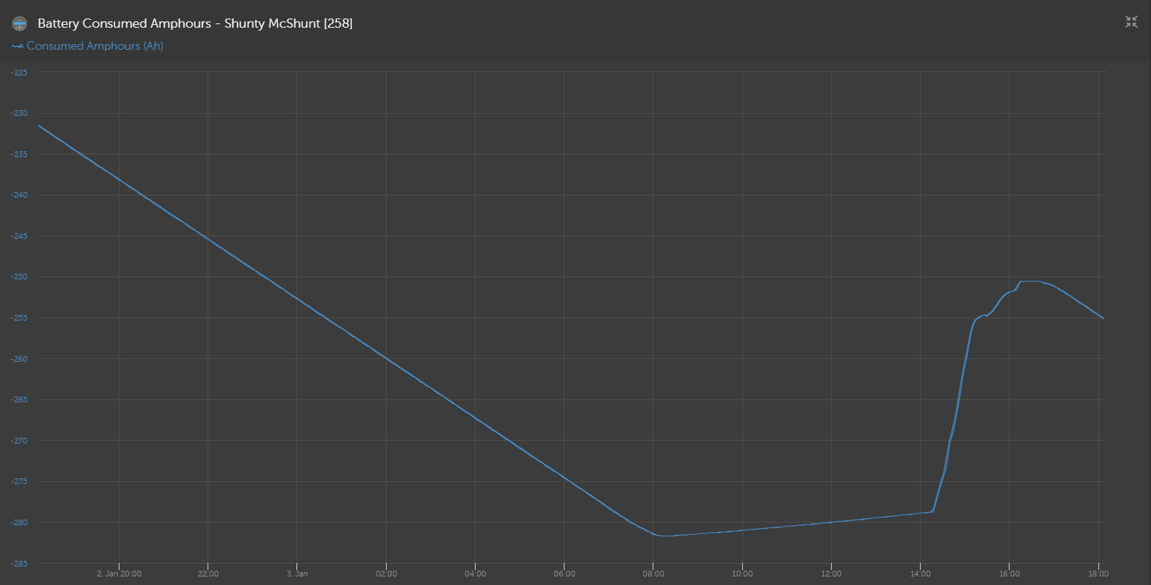
We are only getting 8.5kWh out of the batteries according to the Victron Consumption data.
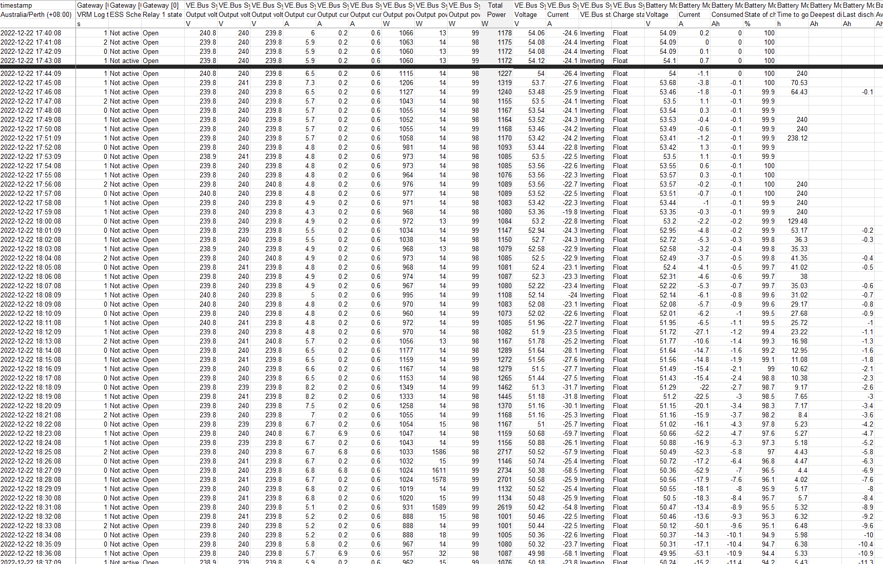
I would love to share the data if someone has time to look at, but I cant attach spreadsheet to this blog. I have attached some snap shots.picture4.pngpicture1.pngpicture5.pngpicture6.png

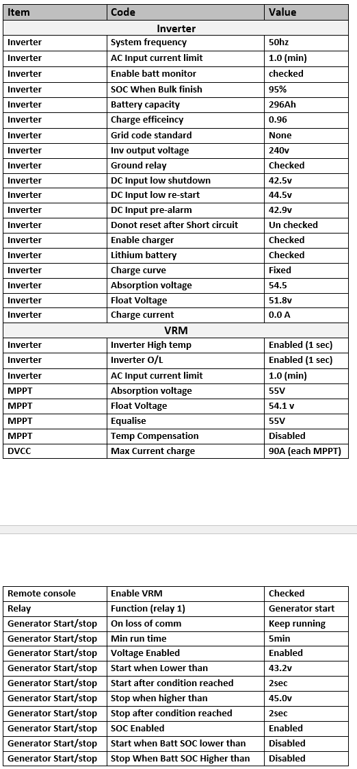
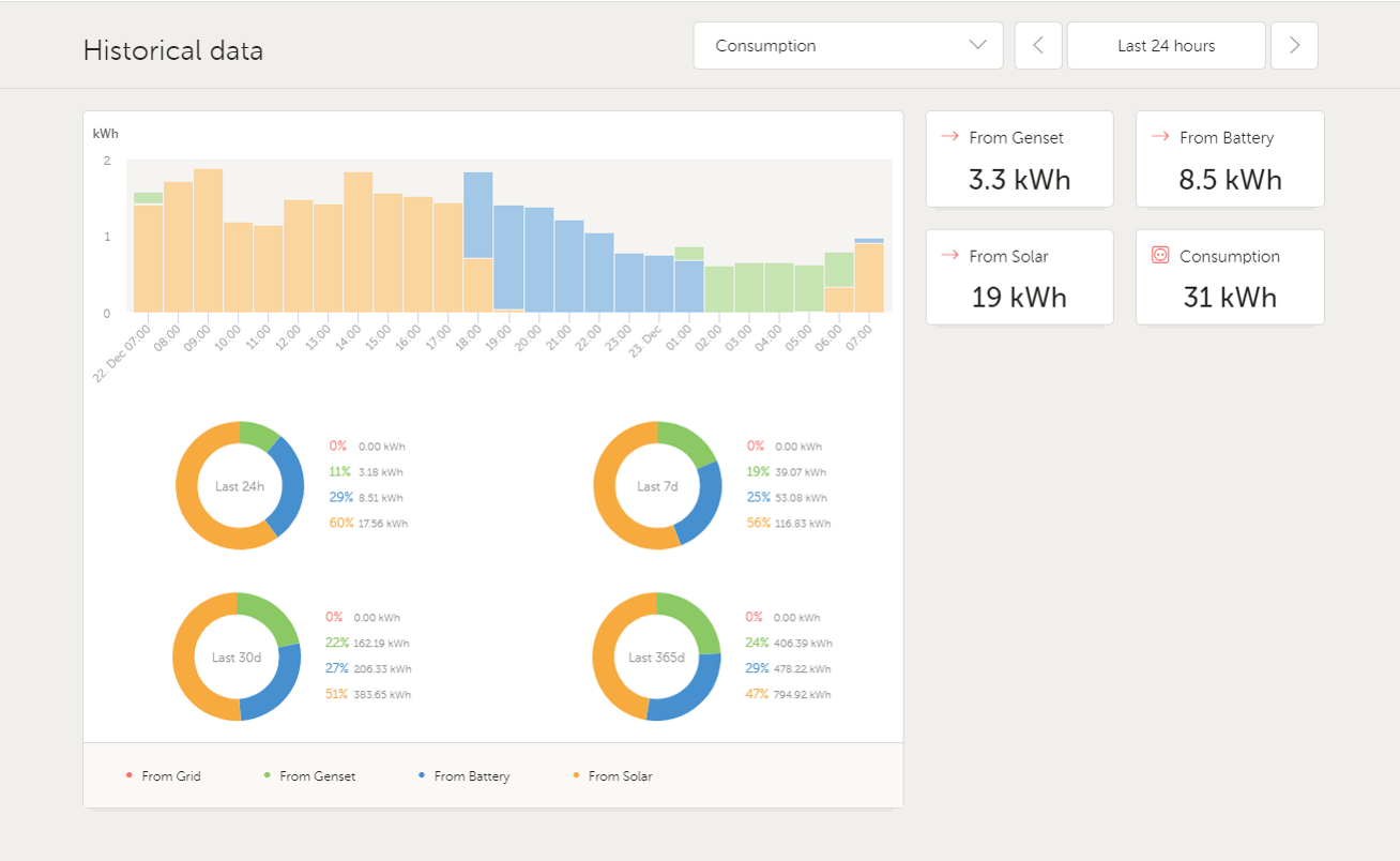
Basically, we are getting 60% of total capacity and I am sure even with the losses calculated, somethings dramatically wrong.

The whole system is new. Zenaji just changed all batteries after rigorous testing and no-one knowing if its the batteries or not. Looks like its not the batteries cos we have the same problem still.

One thing I have noticed is that the 3 phase load is unbalanced and 2 phases are only drawing 14w and 100w on average. Im thinking the inverter efficiency will take effect, but surely not that much?

We are getting to the hotter months now and the system is in a garage with no additional cooling. But atm we are only talking 30C days tops and average of 24C in the last month.

So. Where is my power going or is the consumption figure wrong?
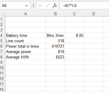
Even average figures from the data, It only adds up to 6.5kWh.
Any help would be great. thanks.

battery capacity
picture4.png (67.5 KiB)
picture1.png (127.4 KiB)
picture5.png (229.8 KiB)
picture6.png (9.7 KiB)
4 comments
2 |3000

Up to 8 attachments (including images) can be used with a maximum of 190.8 MiB each and 286.6 MiB total.

Alexandra avatar image Alexandra ♦ commented ·

@Shannon Lowke

Voltage is not a good indicator for SOC particularly with Lithium batteries.

Are they 12v batteries and you have them in 4s 2p setup? Or are they 48v batteries?

1 Like 1 ·
shannon-lowke avatar image shannon-lowke Alexandra ♦ commented ·
Thanks Alexandra,

They are 48v Batteries.

SOC is a calculation and Voltage is actual, I thought?

So you would get a better accuracy out of a voltage and a more finer tune.

Im not sure if one is better than the other but I lean towards Voltage myself.


0 Likes 0 ·
raymiller avatar image raymiller commented ·
For the size of the inverters ie. 5*3 =15kVA to have only approx 15kWh of storage is very much at the bottom end of matching the inverter to battery capacity to supply the peak currents. Seems you have also only a small about of autonomy, which is a design decision, but the higher the peak power drawn from the batteries the lower the total energy available. My single-phase system using a single 3kVA inverter has 10kWh worth of batteries and I would consider this at the bottom end of battery capacity to match the inverter and as recommended by Victron.

I would highly recommend for any system should have a separate AH counter/ energy counter which looks at all the totals into and out of the battery and removes the guesswork or at least provides an energy counter which can be calibrated for your system.

And as suggested go back to basics when checking your system. Use a professional current meter/clamp and have also a known ac load (unity power factor) at your inverter AC voltage, use this to verify the change in power reading from each inverter (if unable to isolate the connected load) and check then the dc input current and voltage with a professional and calibrated volt meter. Use this to check the Victron readings supplied by your system. If you can get your load up to around 1kW, this load can be used to provide a constant load while you use an mV dc meter measuring each high current connection and device from your battery to inverter input. This really should be done at commissioning to check ALL your high current connections and components (ie fuses, shunts and cable) are indeed as low in resistance as designed.

All the best.


1 Like 1 ·
snoobler avatar image snoobler commented ·
DVCC 90A charge limit is absolute, i.e., regardless of source, it will not allow more than 90A to charge the battery. You indicate "each" - that's not the case. If your desire is to have EACH MPPT sent 90A to the battery, then DVCC should be set to 180A.

If you want to always restrict charging from all sources to 90A, you have set DVCC correctly.
0 Likes 0 ·
5 Answers
jkmann avatar image
jkmann answered ·

Your system is fairly complex, so this is more of a generic answer:

1) Measurement problems, which you can check by comparing a known load to the measured consumption, and also by using a clamp amperage meter to compare a system measurement with your clamp meter. Your numbers are so far off expectation, that a measurement problem should be apparent if that is happening.

2) Unaccounted for loads or resistance, which you can check with a detailed system review and IR camera. You can also measure voltage drops to see if you are losing energy were you shouldn't be.

3) Isolation testing, which basically means testing part of they system and then testing a different part of the system. For example, splitting your battery bank into two and testing each half separately to see if your results are identical.

4) Equipment self-consumption: Problems like you describe sometimes come down to malfunctions or conflicting settings that cause two pieces of equipment to waste energy trying to synchronize with each other, or simply not function efficiently. Sometimes this isn't visible, but it should show up as heat. This could also be in your consuming equipment.

7 comments
2 |3000

Up to 8 attachments (including images) can be used with a maximum of 190.8 MiB each and 286.6 MiB total.

shannon-lowke avatar image shannon-lowke commented ·
Thanks jkmann,

Im thinking I will need to go into more depth like this, so this is very helpful towards my next steps of the process.

Thanks again for your help

0 Likes 0 ·
shannon-lowke avatar image shannon-lowke commented ·
jkmann,

My brain keeps going back to the unbalanced load and the low consumption over the night.

(did you read my original comments and further down after the pictures?)

I'm wondering if the efficiency of the inverter has that much effect when the load is so low over the nighttime. It shouldn't be, but I am gripping at straws.

0 Likes 0 ·
snoobler avatar image snoobler shannon-lowke commented ·

I run 50W EA "background" loads on my Quattro 48/5000. My efficiency is about 60% considering the inverter consumption (about 30W each) and the conversion inefficiencies, i.e., to get that 100W total, my shunt reports 180W consumed.

I expect your 3MP run a total of 90W continuous consumption. That's 2.16kWh every 24 hours, so we're up to about 10.7kWh accounted for.

Inverter idle consumption and efficiency are not considered in consumption.

What does your smartshunt report? It should be configured such that every electron, coming or going, routes through it, and it should report the Ah consumed.


0 Likes 0 ·
shannon-lowke avatar image shannon-lowke snoobler commented ·

Thanks Snoobler.

Im trying to work this out. Stick with me:
Your shunt reports say 180w consumed when using a total of 100w? because of the efficiency losses?

yet "Inverter idle consumption and efficiency are not considered in consumption" So if the smart shunt counts every "electron", how does this work?

Yes, the inverter parasitic load can be 30w and 90 in total lets say. But the batteries only runs for about 9hrs from 100% SOC to about 8% (in this system) so thats only about 0.8kWh over this time (@90w).

Im still missing a massive chunk with 8.5kWh out of 14kWh worth of batteries.


0 Likes 0 ·
snoobler avatar image snoobler shannon-lowke commented ·

Yes. 180W through the shunt with only 100W used in AC loads. The 80W is the self-consumption of the inverters and the power consumed in DC-AC conversion losses.


I should have said "are not considered in AC consumption," i.e., the 8.5kWh to which you're referring. That value represents only the AC consumption provided by battery (AC output). It does not include efficiency losses or idle power consumption.


The shunt Ah consumed is a much more reliable indicator of battery usage.


When you say 100% or 8%, is that the value reported by the shunt or estimated by voltage?

0 Likes 0 ·
shannon-lowke avatar image shannon-lowke snoobler commented ·

Gotchya,

Yes, I am predicting an amount of losses are in there.

The 100-8% is SOC coming from the advanced graghs in VRM

So if we take 8% off the 14kWh then its down to 12.88kWh available capacity.

Take a further 0.8 for the inverters, we have 12kWh

But I am still missing about 3kWh over all. Thats 25% of its available capacity not accounted for. I cant think of anything that major that can be wrong.
But will have to go to site and carry out tests as per jkMann suggested


1672789329610.png

1672789366241.png


0 Likes 0 ·
1672789329610.png (54.4 KiB)
1672789366241.png (74.7 KiB)
snoobler avatar image snoobler shannon-lowke commented ·

Use of the shunt in stating the low SoC is very good news. Now add this widget:

Battery Consumed Amphours:

1672794721788.png


I assume you have the shunt programmed for 296Ah as you do the inverter per your above table. This indicates that you are consuming 92% of 296Ah from the battery.

It would be wise to confirm the shunt reading with a clamp DC ammeter.

If you are not operating each inverter at about 1500W consistently, you are not operating at peak efficiency. Above 1500W, efficiency tapers off slowly to max rated power, but below 1500W, particularly at low power, efficiency can be dramatically lower.

https://www.victronenergy.com/upload/documents/Output-rating-operating-temperature-and-efficiency.pdf

I'm not at all shocked by a 20-25% loss from DC to AC output.


0 Likes 0 ·
1672794721788.png (43.2 KiB)
ffvictron avatar image
ffvictron answered ·

@shannon-lowke : have you synchronized the MPPT battery charger settings to the battery specifics charging, bulk and float voltages? then I'd check for the 100% synchronization of the SmartShunt to show proper 100%.

Another thing that comes to my mind is whether you have created the VE.Smart Networking among the devices, this may help with the system sync, see here: https://www.victronenergy.com/media/pg/VE.Smart_Networking/en/introduction.html

4 comments
2 |3000

Up to 8 attachments (including images) can be used with a maximum of 190.8 MiB each and 286.6 MiB total.

shannon-lowke avatar image shannon-lowke commented ·
Thanks ffvictron

Yes all MPPT settings are in sync.

We have tweaked some settings to get the most out of it and push the envelope.

We do have a voltage drop when a 2kw+ load is applied (about 0.5v) which will drop the inverters out if I dont have this buffer, which is why I set battery low to 43.2v and inverter cut out is 42.5

The smart shunt is networked and I have calibrated it a few times. The variance is under 1v and 2 amps

0 Likes 0 ·
snoobler avatar image snoobler shannon-lowke commented ·

If you have these batteries:

https://www.solarbatteriesonline.com.au/wp-content/uploads/2021/08/A48-40-Spec-Sheet-V4.1-HQ.pdf

Based on the 56.5V charge voltage, I wouldn't say you're "pushing the envelope" at 55V.

IMHO, 0.5V drop on 40A load is huge. You have a problem somewhere unless your battery cables are 50 feet long. Check all connections and confirm wire size is adequate.

Shunt variance of 1V and 2A sounds horrible to me.

0 Likes 0 ·
shannon-lowke avatar image shannon-lowke snoobler commented ·
Thanks Snoobler,

Im trying to not get confused here and maybe need to explain further.

The shunt value as to meter value could be as simple as a meter calibration or time lag and it is constantly fluctuating so, considering the shunt was calibrated, I am putting this to the side a bit (considering the massive indifference of capacity/consumption results)

Pushing the envelope is more for the battery cut out. not charging.

The voltage drop when a load is instantly applied and is the current spike. IE when the battery cut out is right on the limit of 43.2V and old mate chucks his aircon on, then it drops instantly and threatens to take the Inverter out on low input shutdown if I dont get the balance right. I have set the battery cut out to lag for a few seconds too. Most the time the volt drop is only 0.1 - 0.2 when an instant load is applied but I have seen a few higher.

0 Likes 0 ·
snoobler avatar image snoobler shannon-lowke commented ·

When this limit is reached, what does the shunt report for SoC?

0 Likes 0 ·
Paul B avatar image
Paul B answered ·

I Agree with Alexandra, SOC so not a good indicator .

always go with battery voltage AT THE BATTERY and as a general rule for LifP04 batteries this is always 100% correct . Voltage is King.

40v is 100% flat at a very low amp draw rate ie under 5% of bank size

56 v is 100% full when amps are below 5% of bank size

Again re the above voltages - this depends on manufactures specs


The 40v low figure you should never go near this level as 40v or 2.5 v on any one cell - but for testing purposes to see if the bank has its full rated capacity it maybe acceptable. you must read the battery specs and run by there suggestions. the above is just a typical bank example.


also its important to have a balanced bank meaning that all cells are at 3.5v when full and that all cells are close to the 2.5v mark when empty.

if you have a week cell then this will cause the battery to shut down once that cell reachs 2.5v or whatever the Vmin cutoff is set to in the batteries BMS


2 |3000

Up to 8 attachments (including images) can be used with a maximum of 190.8 MiB each and 286.6 MiB total.

shannon-lowke avatar image
shannon-lowke answered ·

Thanks Paul B

The batteries have been changed out even though we presumed they are ok.

Some results suggested a breakdown in cells. Unfortunately the site is remote and I had a contractor (no experience on victron) doing the testing under instructions but it was hard to get him to do it properly and record the results accurately.

They are being tested in the factory as soon as they arrive back.

However, the new batteries were tested prior to install and we are still having these issues.

I have worked very closely with Zenaji on the specifications and we are happy with the settings.

They too do not understand the results.

It just doesnt make sense that Victron is saying we are using 8.5kWh of storage yet we have 14kWh worth and the settings are at 90% capacity out of the batteries.

1 comment
2 |3000

Up to 8 attachments (including images) can be used with a maximum of 190.8 MiB each and 286.6 MiB total.

snoobler avatar image snoobler commented ·

So after using 8.5kWh, shunt is reporting 10%, or is the "10%" based on voltage? If voltage, you're chasing a lie.

Per above, inverters are consuming 2.16kWh/day in idle consumption. If that consumption is over the course of two days:

8.5+2.16 = 10.66kWh

10.66kWh/0.9 = 11.84kWh - getting closer to

Conclusions:

Fix connection issues: 0.5V on 40A is too big of a drop.

Use shunt exclusively to determine actual battery consumption and re-evaluate if you have an issue at all.


0 Likes 0 ·
shannon-lowke avatar image
shannon-lowke answered ·

Thanks you all for your assistance.

I have gone to site and found the issue.

Firstly the shunt was out and reading 2 amps different to the actual so I carried out a zero current calibration.

But the obvious reason was that 3 of the 8 batteries had tripped. (all makes sense now)

My theory is that the installer (not 100% up with battery theory) has chucked them in and the Battery voltages were not equalized. This meaning the 3 took the hit of the maximum charge current and tripped the 40A breakers in the battery. (the site is remote so we couldn't just attend immediately)

I charged the batteries close to the same voltages and then removed main fuses (load), left all batteries on so they equalized over a further hour.

The system is now functioning correctly and we are getting the true Capacity results.

All answers have been a great input and learning exercise, so thank you again.


2 |3000

Up to 8 attachments (including images) can be used with a maximum of 190.8 MiB each and 286.6 MiB total.

Related Resources

Additional resources still need to be added for this topic