question

francoisemslie avatar image
francoisemslie asked

Multiplus 12/1600/70 not delivering and or maintaining high charge current

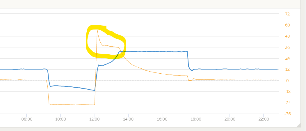
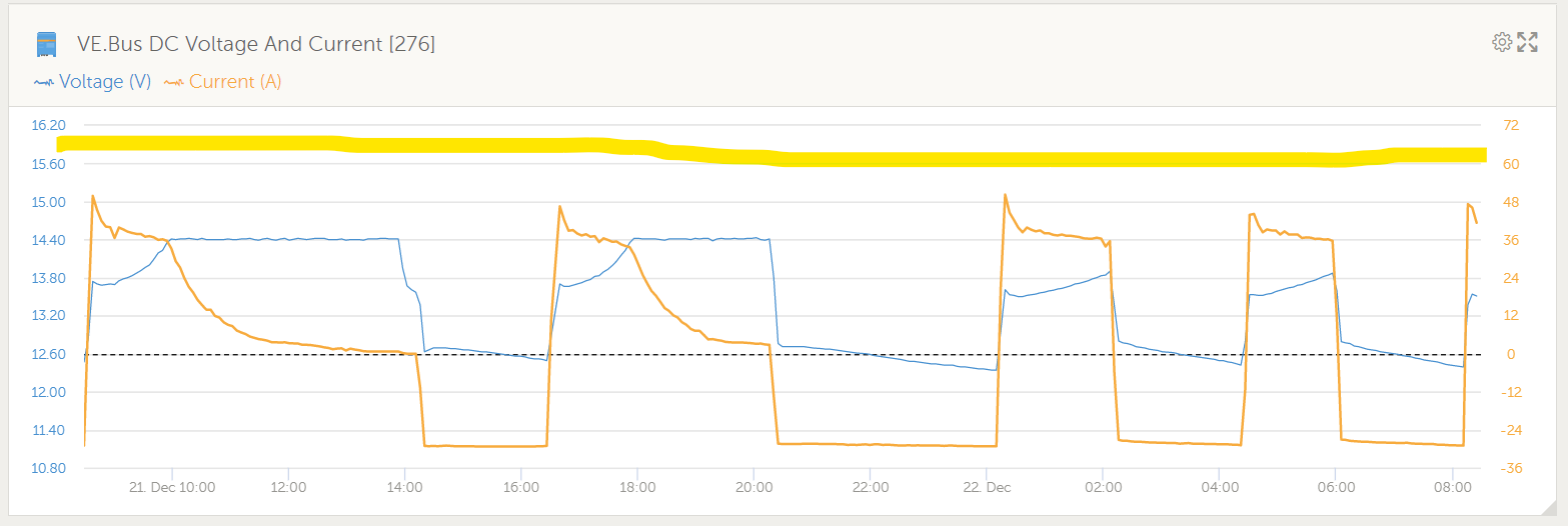
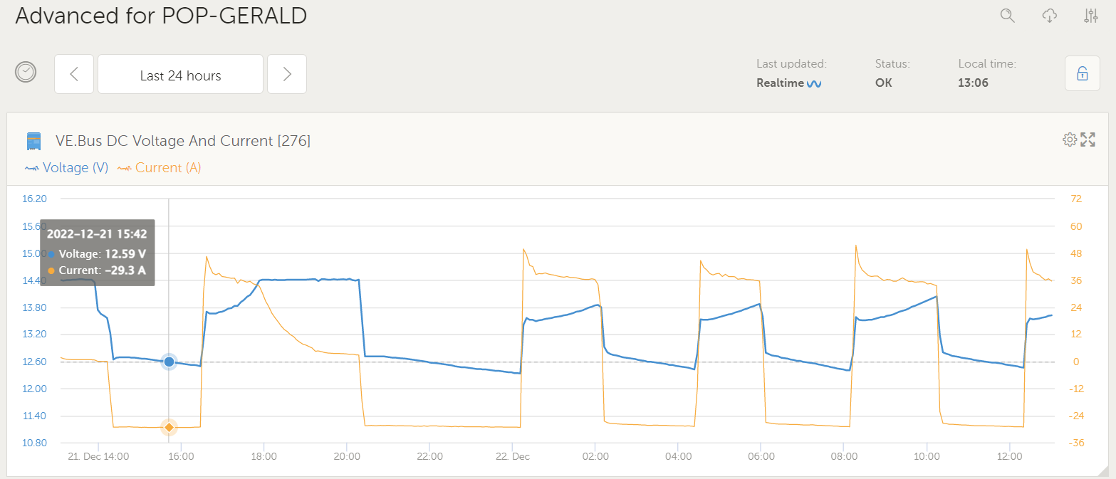
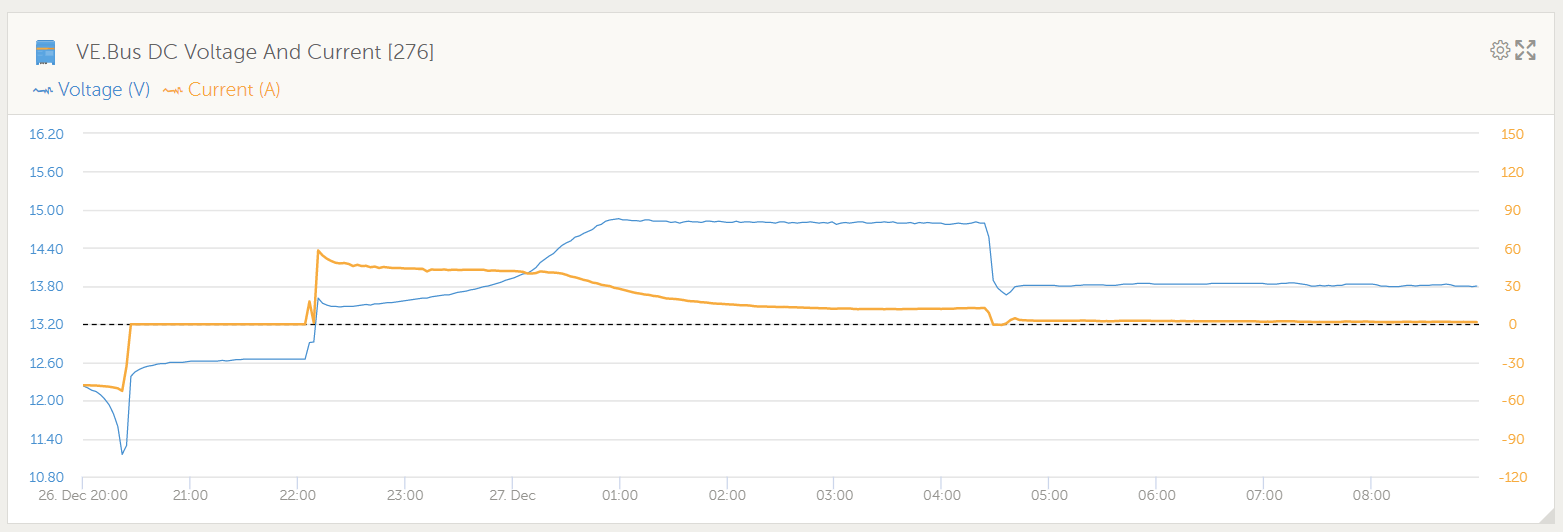
Below image from VRM of charge cycle being delivered.

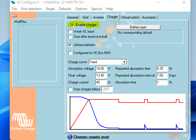
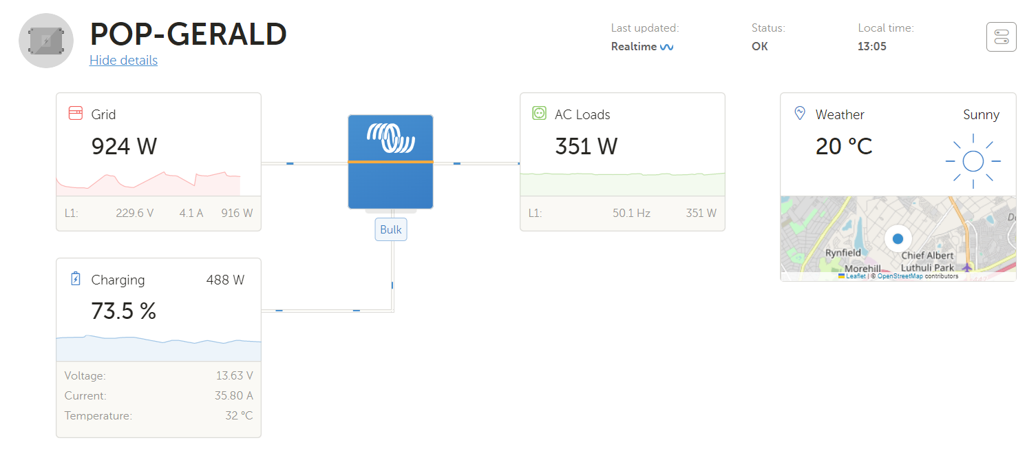
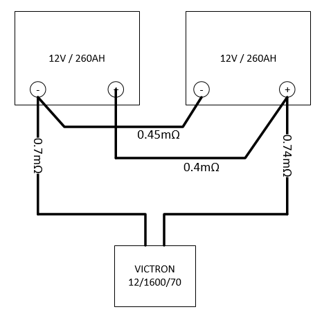
The battery is 2 x GEL 260AH units in parallel, result 520AH. I have around 10 of these sites all with the same 12/1600/70 unit and 520AH battery, they all do the same. The charge current peaks at the set 55A for a very short time and then drops to <40A for the rest of the bulk charge phase, well before the 14.4 set point is achieved. I have read as many posts on this issue and there does not seem to be a real answer anywhere for this problem. My local Victron supply agent has no answer for me either. Actually I would like around 60A charge current as I need to recover these units as fast as possible.

Has anyone found the reason why these units do not maintain the high level of charge the spec sheet seems to indicate is possible?

1670619244994.png

charge current limit
1670619244994.png (24.5 KiB)
1 comment
2 |3000

Up to 8 attachments (including images) can be used with a maximum of 190.8 MiB each and 286.6 MiB total.

kevgermany avatar image kevgermany ♦♦ commented ·

Please repost the graph with both scales showing.

0 Likes 0 ·
11 Answers
JohnC avatar image
JohnC answered ·

Hi @francoisemslie

Distortion on the same ac phase may cause this. Something like an inductive load causing poor power factor, or some weird sine chopping device. Might be something easy to test for by switching off the loads.

2 |3000

Up to 8 attachments (including images) can be used with a maximum of 190.8 MiB each and 286.6 MiB total.

francoisemslie avatar image
francoisemslie answered ·

The load is a bank of network switches. The unit is acting as UPS in a telecom cabinet.

2 |3000

Up to 8 attachments (including images) can be used with a maximum of 190.8 MiB each and 286.6 MiB total.

francoisemslie avatar image
francoisemslie answered ·

Well I see no help on the subject. I have many of these 1600VA multiplus units in the field all doing the same thing and just no help. I am so disappointed in the Victron support concerning this problem. After getting our company management to convert all sites to Victron I now have to try explain why we can't get the units to deliver charge current as expected, I can only assume that the Victron specifications are not really something to be believed.

2 comments
2 |3000

Up to 8 attachments (including images) can be used with a maximum of 190.8 MiB each and 286.6 MiB total.

klim8skeptic avatar image klim8skeptic ♦ commented ·
Where are your screenshots?
0 Likes 0 ·
kevgermany avatar image kevgermany ♦♦ commented ·
We try to help, but with insufficient information we're blind.
0 Likes 0 ·
Guy Stewart (Victron Community Manager) avatar image
Guy Stewart (Victron Community Manager) answered ·

Hi @francoisemslie,

Do you have a charge current limit set in VEConfigure?

If so, is it possible to set that to the maximum (in this case 70A) and see if it makes any difference to charging performance?

This can be checked and performed remotely via Remote VE.Configure - https://www.victronenergy.com/live/vrm_portal:remote-veconfigure

5 comments
2 |3000

Up to 8 attachments (including images) can be used with a maximum of 190.8 MiB each and 286.6 MiB total.

francoisemslie avatar image francoisemslie commented ·

I have changed 5 sites to max charge setting of 70A. I will monitor them over the next two days and report back.

1 Like 1 ·
francoisemslie avatar image francoisemslie commented ·

Hi @Guy Stewart (Victron Community Manager)

None of the 5 sites that I increased all the way to 70A have got anywhere close to delivering the 70A charge current. Below is one of the sites last 24 hours DC bus data. You can see small peaks as the charge charge cycle starts, still not close to 70A as setup and drops down very fast to around 40A. I have marked the 60A line, not even getting to that. Some of the sites don't even show this peak, charge current only ever starts at around 40A.

These sites temperature runs around 30 to 38 deg C as measured by battery temperature probe, over the last week. I have had no high temperature alarms reported by Victron unit when checking Cerbo GX notifications. These sites either have 2 or 3 12V/260AH GEL batteries connected in parallel. I have set up a unit on the bench in a environment that is around 25 deg C and get the same results. I really need to know why these units across our network will not deliver charge current as expected as due to the regular grid failures we have I need to recover the charge as fast as possible each time. It honestly looks like a design shortcoming on this model and need to get an answer as to why this unit will not deliver as expected. I have a 12/1200/50 unit purchased, placed that on test and the unit will deliver 40A to 45A no problem under the same conditions, so if you compare output as a percentage of rating its over 90%, again why does the 12/1600/70 not do this?


1671690625160.png

0 Likes 0 ·
1671690625160.png (58.1 KiB)
Matthias Lange - DE avatar image Matthias Lange - DE ♦ francoisemslie commented ·
Can you please make some screenshots of the VE.config settings?
0 Likes 0 ·
nickdb avatar image nickdb ♦♦ francoisemslie commented ·

The obvious answer is that it is derating. 38C ambient is high, the internal temp will be much higher so it is quite likely you are being derated to 800W.

You have given nothing much to help diagnose, as others have already stated.

Assuming around 13V charging and from the one chart, around 38A, that equates to around 500W. What is the active load? If it is anywhere near 300W then that's the most likely answer.

You can't expect to put any device into such high temps and not up-size it to compensate.

Fail to plan, plan to fail.

A separate point, these systems don't do voltage "smoothing" so as a UPS for sensitive gear, they aren't the best option as voltage fluctuations from grid will pass through until cut-off limits are hit,sometimes causing dips or restarts. That may not be a consideration for you as they definitely are a lot cheaper than the alternative.

0 Likes 0 ·
nickdb avatar image nickdb ♦♦ francoisemslie commented ·

Something else to consider, if you want those batteries to last, you shouldn't be charging above 52A anyway.

Also, if this environment is correctly configured, temp compensation should be dialling back the voltage.

Using victron batteries as an example, they should be adjusted by 24mv/C or 0.3V at 38C, this will also affect how they charge.

At those temps, the battery life is somewhat drastically reduced.

0 Likes 0 ·
snoobler avatar image
snoobler answered ·

@francoisemslie

Before you get indignant and huffy, you really need to be forthcoming with information. We shouldn't even have to ask.

Describe your system (AC loads, DC loads, etc.), post your hardware, all your VEConfig settings, and your DVCC settings.

2 |3000

Up to 8 attachments (including images) can be used with a maximum of 190.8 MiB each and 286.6 MiB total.

francoisemslie avatar image
francoisemslie answered ·

@snoobler

I will add all the info shortly. Can you indicate how to upload the VE.Config file, the upload won't accept the file.

2 comments
2 |3000

Up to 8 attachments (including images) can be used with a maximum of 190.8 MiB each and 286.6 MiB total.

love2learn avatar image love2learn commented ·

Why do you have "Lithium batteries" checked?


When on a different AC source, all that power is passed through, so you need to subtract the running AC loads from the incoming total from what you see going towards charging the batteries.

  • Quote from Multiplus manual:
  • "PowerControl - Dealing with limited generator, shore side or grid power The MultiPlus is a very powerful battery charger. It will therefore draw a lot of current from the generator or shore side supply (nearly 20 A per 3 kVA MultiPlus at 120 VAC). With the Multi Control Panel a maximum generator or shore current can be set. The MultiPlus will then take account of other AC loads and use whatever is extra for charging, thus preventing the generator or shore supply from being overloaded."


I only get about 1000-1100watts when charging from my generator, but I also have about 300watts of AC loads running, so minus inefficiency that should add up to about 1500 max expected from that generator outlet.


Your VEConfigure screenshot shows that your charge current is set to 40amps....


Also, can you post the rest of the VEConfigure tab screenshots?


What do you have configured for "Shore limit->AC input current limit"? It's under the "General" tab. And are the "Overruled by remote" and "Dynamic current limiter" options checked?

1 Like 1 ·
klim8skeptic avatar image klim8skeptic ♦ commented ·

Post screenshots..

eg , every tab pls.ac-charge.png

0 Likes 0 ·
ac-charge.png (64.5 KiB)
francoisemslie avatar image
francoisemslie answered ·

@snoobler

d41243b5183d_inst_ttyS4_Interfaces_Mk2_Tunnel (3).zip

ritar_12V_260Ah_datasheet.pdf

Hi,

  • Attached VE.Config file.
  • If you look at earlier posts, the load is a collection of network switches managing a fiber network in a street cabinet, we have 43 Victron sites like this scattered around the area we service.
  • For this particular site the AC load is 351 W, see VRM dashboard below.
  • Below latest 24 hour VE.Bus DC data.
  • You will see the regular grid fail cycles this site is exposed to.
  • You will see how the charge current does not get anywhere close to the set 70A, all sites have the same issue were I have the 12/1600/70 deployed.
  • Site battery is 2 x 12V/260AH Ritar GEL batteries in parallel, also mentioned in first post.
  • Each battery is connected to the Victron unit with 1m of 10mm square cable.
  • These batteries can be charged at 78A each as specified in spec sheet, see attached.
  • On the Cerbo GX, DVCC is turned off.
  • I have setup the battery in VE.Config as a lithium battery to try avoid any GEL type current limitations that might be applied, has made no difference. Have the battery absorb and float set to GEL specific values in the Lithium profile, 14.4 and 13.5. Fiddled with these settings, again made no difference.
  • I have some 12/800/35 units and 12/1200/50 units in the field, these are able to deliver at least 30A and 45A as required, over 90% of max rated charge.


1671707131554.png

1671707179961.png


1 comment
2 |3000

Up to 8 attachments (including images) can be used with a maximum of 190.8 MiB each and 286.6 MiB total.

love2learn avatar image love2learn commented ·
So your screenshot shows charging at 13.6v * 35.8a = 488w. Your AC loads are consuming 351w and you have a total of 924w coming in from the grid. AC + charging total is 839w. So about 85w is unaccounted for. How much DC power is being used?


Can you enable "Has DC System" in your Cerbo GX? We need to see what the DC loads are.


Im more curious about why you're only pulling in 924w (4.1a) from the grid since you have AC input current limit set to 12a. This number may only apply to the PowerControl and PowerAssist features in the inverter? The transfer switch max is 16a, which means you should be able to pass through 3680watts no? Or am I incorrect? I can't seem to find a whitepaper that shows what the max grip power input is on these units.


Another contributing factor I see is your high ambient temperature. The datasheet for your inverter shows continuous output power being 1300w @ 25C, 1200w @ 40C, and 800W @ 65C. Also, the max inverter efficiency is rated at 92%.

0 Likes 0 ·
nickdb avatar image
nickdb answered ·

@francoisemslie turn off power assist and disable your input current limit (set to 12A currently), then see if it improves.

2 comments
2 |3000

Up to 8 attachments (including images) can be used with a maximum of 190.8 MiB each and 286.6 MiB total.

love2learn avatar image love2learn commented ·
How do you disable AC input current limit? I dont see a checkbox in VE Configure for that.
0 Likes 0 ·
nickdb avatar image nickdb ♦♦ love2learn commented ·
Bad choice of words. Set it to the maximum, should be 16A iirc.
1 Like 1 ·
snoobler avatar image
snoobler answered ·

@francoisemslie

10mm cable for 70A is inadequate. 50mm is recommended in the manual.

Those are AGM batteries, not GEL. Important because if they were GEL, your charge voltage would kill them. AGM allow higher charge voltage. While I understand this doesn't solve your problem, it does address your need. Increase absorption voltage to the 14.8V, and you will have faster charging during longer grid-up periods.

By specifying Lithium Battery, you have disabled temperature compensation. At 30-38°C, charge voltage should be lower than the spec for 25°C. Per the battery datasheet, it should be -4mV/°C/cell. Fortunately, 14.4V is still below the compensated voltage of 14.48°C as calculated from 14.8V @ 38°C. You can specify the desired charge parameters and then create a new battery type. There are no current restrictions inherent to GEL, and nor should GEL have been specified in the first place.

Cycle life operating at 30-38°C is going to be notably reduced from spec. Expect cycle life reduction of as much as 50%.

While the above doesn't address your concern, it's important that a system be designed and installed properly. The items mentioned are not consistent with good design or installation practices.

It's known that the MP begins to throttle charging at 40°C. With them in continuous operation with at least 30W of continuous waste heat, it's almost a certainty that they are over 40°C internally, so you should expect reduced performance. What is your firmware version? In 496, a change was made to improve the fan algorithm.

Summary:

  1. Increase wire gauge.
  2. Per @nickdb increase AC input current to 16A and disable powerassist
  3. Create a custom battery type as described with 14.8V absorption, 13.8V float and -24mV temp compensation.
  4. Reduce temperature of operating environment and/or provide external cooling.
  5. Upgrade to firmware 496 (assuming it's appropriate for your unit).


2 |3000

Up to 8 attachments (including images) can be used with a maximum of 190.8 MiB each and 286.6 MiB total.

francoisemslie avatar image
francoisemslie answered ·

@snoobler & @nickdb

  • I am using 10mm cable per battery, so each cable is only required to carry 35A, 10mm cable is more than adequate for this.
  • Firmware is 498
  • I will setup the same site arrangement in my test lab were temperature is around 25 deg C constantly and do simulations.
  • Once the test is setup and running I will report back.
1 comment
2 |3000

Up to 8 attachments (including images) can be used with a maximum of 190.8 MiB each and 286.6 MiB total.

Alexandra avatar image Alexandra ♦ commented ·

@francoisemslie

The manual recommended cable size is much larger, if it is not installed to recommend spec, then how is it to perform to the full spec?

FYI incoming AC cable resistance (length and size) also affects charge rate.

Derating due to internal heat is a thing as well. So ambient while it affects the start point does not reflect internal components temps.

Have you tried individually bus barring the setup, so you are not passing charge current over the 10mm cable through lugs (extra resistance). And stacked ones at that? Resistance equals heat, heat is energy loss.

I am also agree that 10mm is too small for a 12v setup. Even on a 48v system I would use 16mm² for 70A for each individual battery.

In every setup resistance is the key.

All the rest of the answers and comments here also have good pointers.

0 Likes 0 ·
francoisemslie avatar image
francoisemslie answered ·

@snoobler & @nickdb & @Guy Stewart (Victron Community Manager)

Below bench test setup and results:

  • Unit set to 70A charge, see attached updated VE.Configure file.
  • You can see how current peaks almost at 60A for a very short time then drops to around 45A.
  • From the cable setup, the total volt drop at 70A would be around 166mV.
  • AC load is around 500W of lighting.
  • I switch off the AC load when running the charge cycle, to limit light on time.
  • Why won't the unit deliver the 70A or even 60A charge with this setup?

48e7da8a24f3_inst_ttyS4_Interfaces_Mk2_Tunnel (9).zip

1672160903848.png


1672159682338.png

1672159722664.png


2 |3000

Up to 8 attachments (including images) can be used with a maximum of 190.8 MiB each and 286.6 MiB total.

Related Resources

Additional resources still need to be added for this topic