question

kogut avatar image
kogut asked

Connection of two MPPTs to the batteries

schemat-5.png


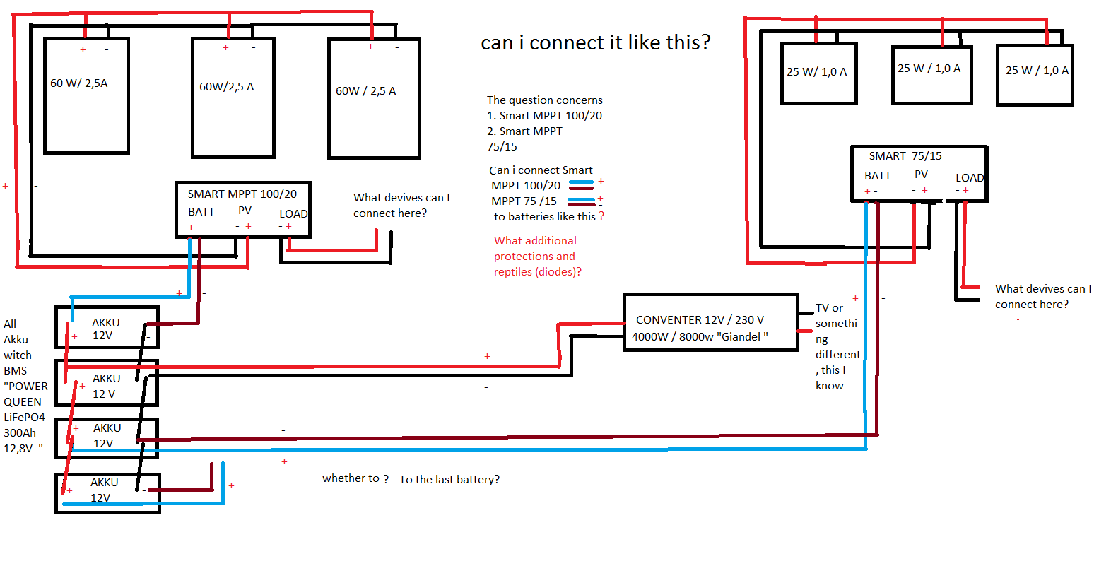
The number of solar panels is more , this is just a pictorial representation of the question. For Smart MPPT 100/20 ( 8*60W or 6* 60 W / 3,0 A ,connected in parallel ) not more than 20 A .For Smart MPPT 75/15 ( 8*15W / 1.0A connected in parallel ) not more than 15 A. I will calculate the power of solar panels here, I do not need help in this matter.
The main question is can I connect Smatr MPPT 100/20 and Smatr Mppt 75/15 to such batteries ( connected in parallel )? (see diagram) . Theoretically : The first battery (connected in parallel) is charged with the Smart MPPT 100/20 and the third or fourth with the Smart MPPT 75/15. The 12v/230v converter draws power from the middle battery (connected to the second or third battery). So, the path of current draw to the converter from the batteries is shorter and the path of charging the batteries is optimal.
Is this solution correct? Will there be interference between Smart MPTT? Or what protections should be added to the wires (diodes)?

I don't want answers like "get yourself an inverter or a bigger Smart MPPT, like 5000/500"

Please don't tell me watts and amps,I know how to add Amps or Volts.

The main question is, is it possible to connect two Smart MPPTs to the batteries?
And possibly what diodes to use (reverse current, battery discharge, etc.)
MPPT SmartSolar
schemat-5.png (40.5 KiB)
1 comment
2 |3000

Up to 8 attachments (including images) can be used with a maximum of 190.8 MiB each and 286.6 MiB total.

kevgermany avatar image kevgermany ♦♦ commented ·

Guessing that what @Steffen Graap was meaning with his suggestion is that your schematic wiring is not ideal for the batteries.

Ideally connect all batteries with equal length and size wires using negative and positive busbars. Connect the chargers and loads to the busbars.

If you can't do that, connect all negatives together, all positives together take the positive from one end of the chain and the negative from the other end.

Both solutions will equalise the charging and use of the batteries.

0 Likes 0 ·
5 Answers
steffen-graap avatar image
steffen-graap answered ·

You can connect MPPT in Parallel, no Problem.
For right Battery-Connection, please read The Wiring Unlimited book from Page 16

2 |3000

Up to 8 attachments (including images) can be used with a maximum of 190.8 MiB each and 286.6 MiB total.

ahtrimble avatar image
ahtrimble answered ·

The short answer is "yes".

But, the method of connection is important, at least to me.

I am doing the same thing here at my off-grid home. I am not seeing any fusing or CBs or switching in your diagram. I am using a PowerIn to parallel my batteries, then the Lynx shunt (connects to my Color Control) with fuse, then another PowerIn to bring in the 2 MPPTs and output to the inverter. Makes it a pretty clean and safe install.

vpost.jpg


vpost.jpg (158.7 KiB)
2 |3000

Up to 8 attachments (including images) can be used with a maximum of 190.8 MiB each and 286.6 MiB total.

ahtrimble avatar image
ahtrimble answered ·

Great point! Thank fully I can set parameters on the MPPT to help with that. Also, the 2 LifePo4 batteries can handle 100a of charge each. I will make sure I will have the MPPT shut down at about 95% or so. And I will be adding 2 more batteries as well, both capable of 100a charging.

As I understand the built-in battery BMS's, they will shut off the charging above 100a.

And, if I calculated correctly, the max my arrays can produce is 107a at 100% efficiency, peak time of day. Spread that out over 4 batteries...I think I should be fine.

Do you agree or see a flaw there?

2 |3000

Up to 8 attachments (including images) can be used with a maximum of 190.8 MiB each and 286.6 MiB total.

Fideri avatar image
Fideri answered ·

@AHTrimble

Did you implement your solution? What were the results?

My potential set up is similar but instead of the Victron Lynx bus bar, I have a custom one with one (instead of your 2) Victron Quattro for inverting only, so no generator. I'm planning on 4 sets of lithiums instead of two. I have one Cerbo GX to read the lithiums and control the MPPT, a Victron 250/100.

In summary, two questions:

1. Did you successfully implement your solution?

2. Why do you have no GX device? Is it redundant?

Fideri

1 comment
2 |3000

Up to 8 attachments (including images) can be used with a maximum of 190.8 MiB each and 286.6 MiB total.

ahtrimble avatar image ahtrimble commented ·

@Fideri

Yes, I implemented it and it has been working flawlessly for months now.

I already had a Victron Shunt and Color Control.

For clarification...One PowerIn was a busbar for my batteries, the other PowerIn was connecting the 2 Quattros and 2 MPPTs. There is a Class T between them.

FWIW...I feel there are 2 requirements for my genset; 1) To keep the house up and running when/if I shut down the solar side for work/maintenance, 2) To charge my batteries if I get a string of cloudy or snowy days.


0 Likes 0 ·
Fideri avatar image
Fideri answered ·

@AHTrimble

That's very helpful. Thank you.

Fideri

6 comments
2 |3000

Up to 8 attachments (including images) can be used with a maximum of 190.8 MiB each and 286.6 MiB total.

ahtrimble avatar image ahtrimble commented ·
Forgot to mention...I went with a total of 3 LifePo4 batteries. 2 - 205ah and 1 - 230ah. The 200+ah batteries are more economical for me vs 100ah LifePo4s.
0 Likes 0 ·
Fideri avatar image Fideri ahtrimble commented ·

I suppose you connected the 3 batteries to the same Lynx Power-in? Any particular reason you went with 2 "Power-ins" instead of one "Power-in" plus one "Distributor"?

They both look the same to me anyway.

1 Like 1 ·
ahtrimble avatar image ahtrimble Fideri commented ·
The first PowerIn is for the batteries...worked perfectly...still have two open spaces for more batteries...if I can ever afford more.

I didn't go with the Distributor because it was considerably more expensive and I didn't need the pretty lights or its computer board telling me when a fuse blew. So yes, that means I did the 'hack' to add fuses to another PowerIn. < click here to see that hack of mine > (also shows connecting my Class T fuse)

FWIW, not using a Distributor removes one more point of failure due to electronics. I kinda like the KISS methodology as much as practical.


0 Likes 0 ·
Fideri avatar image Fideri ahtrimble commented ·
I have read both your articles on the Power-in. Good job.
0 Likes 0 ·
ahtrimble avatar image ahtrimble Fideri commented ·
For the record...the wiring diagram is now outdated. I can send you a picture of the system "as is" if you would like.
0 Likes 0 ·
Fideri avatar image Fideri ahtrimble commented ·
Understood. A picture would be great: info@ntindaview.com
0 Likes 0 ·

Related Resources

Additional resources still need to be added for this topic