question

michaelvh avatar image
michaelvh asked

3-phase ESS unnecessarily feeds the grid when phase loads unbalanced

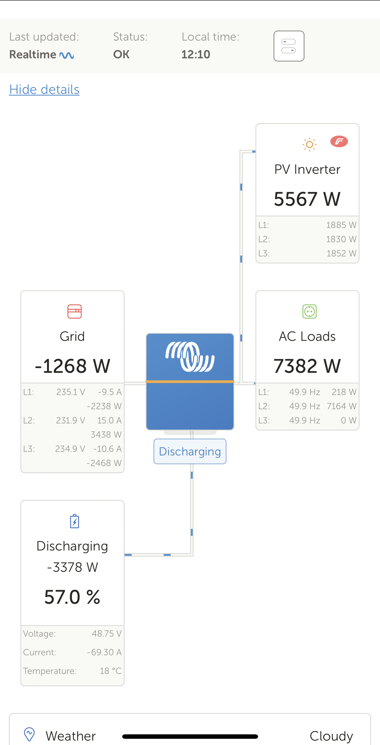
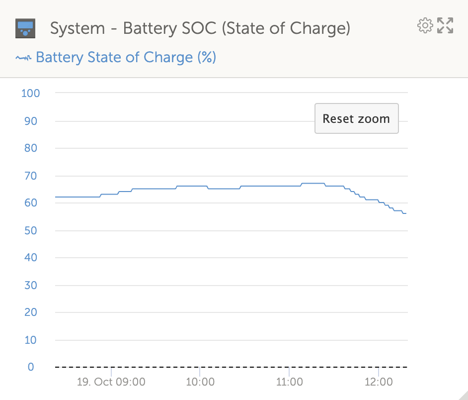
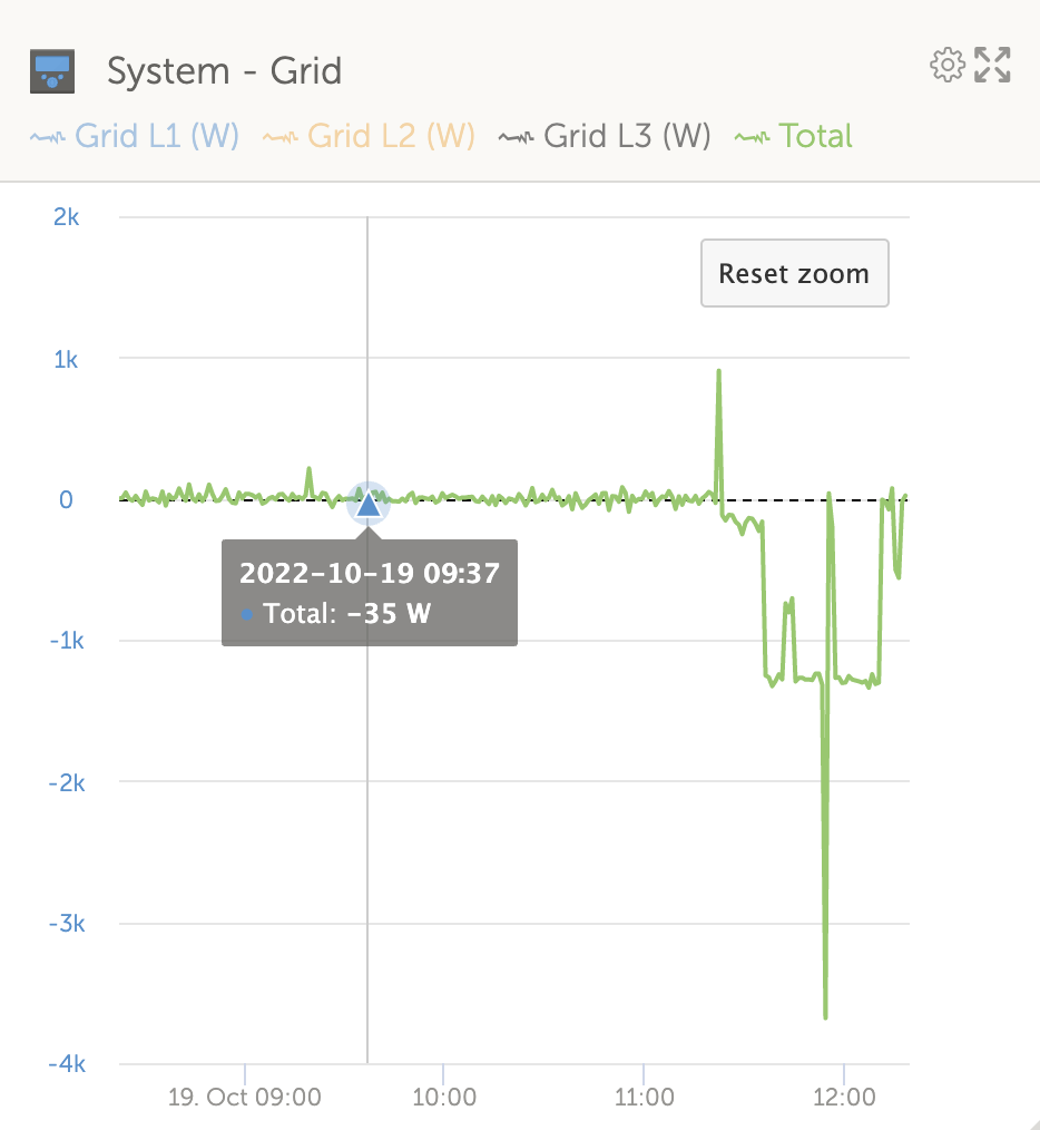
My ESS system starts feeding the grid from the battery when I put a high load on one of the 3 phases, while the other two phases are almost not loaded. This seems to be a reoccurring problem after a few tests.

Phase compestation is set to "total of all phases". The grid setpoint is set as +10w.

When all 3 phases are sort-of equally loaded, high or low load, this does not happen.

Any ideas what is going on here?

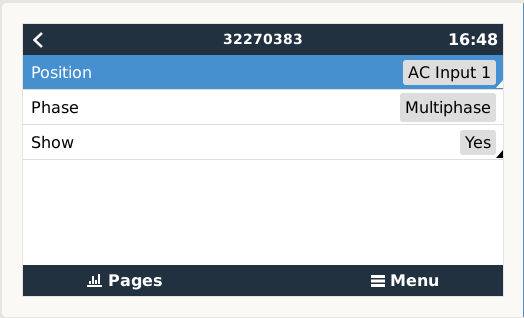
ESS with 3x multi 3K, AC coupled with 10kw Fronius symo (on AC-in, vrm dashboard incorrect due to using external current transformers) , 8x pylontech US2000C

The multi's use 3 external current sensors which are correctly installed with the 5 meter wires.

EDIT: this seems to only happen when the total load is higher than the PV output, and when above 24A (+-5,5kW load on one phase)

img-5555.pngscreenshot-2022-10-19-at-124213.pngscreenshot-2022-10-19-at-124151.png


ESSess discharging
2 |3000

Up to 8 attachments (including images) can be used with a maximum of 190.8 MiB each and 286.6 MiB total.

4 Answers
marekp avatar image
marekp answered ·

@MichaelVH

Try setting "individual phase" but sudden changes in load result in short power imbalance.

BTW.

You cannot have 10kW Fronius on the AC-out of 3xMP/3k.

21 comments
2 |3000

Up to 8 attachments (including images) can be used with a maximum of 190.8 MiB each and 286.6 MiB total.

michaelvh avatar image michaelvh commented ·

It seems like it is not a short power imbalance, but sustained once going over 24A on one phase.

No worries, the AC inverter and all loads are on AC-in, the VRM dashboard shows it on AC-out because we are using external current transformers for measurement

0 Likes 0 ·
marekp avatar image marekp michaelvh commented ·
@MichaelVH

I do not know how the power calculations perform if system thinks that your Fronius is on AC-out when in reality is on AC-in.

0 Likes 0 ·
michaelvh avatar image michaelvh marekp commented ·
As far as i know, and to my experience, it calculates exactly as all loads and inverters would be on AC-out and it does so correctly. The external sensors replace the internal sensors all together so the MP is not even aware that it has a sensor attached.
0 Likes 0 ·
marekp avatar image marekp michaelvh commented ·

@MichaelVH

But MP is not the one doing the power calculations.

Where in your GX you have Fronius situated?

screen-shot-2022-10-19-at-44752-pm.png

0 Likes 0 ·
michaelvh avatar image michaelvh marekp commented ·
Sorry, the GX indeed (inside one of the MP), the fronius is configured as AC-out as otherwise there is no display of the Fronius on the flow charts, and the grid would always show negative values.


To be more clear, the unwanted feed in as described above also shows on the grid utility meter itself, so that would be correct.

0 Likes 0 ·
marekp avatar image marekp michaelvh commented ·

@MichaelVH

If you tell you GX that Fronius is on AC-out when in reality is on AC-in all power calculations and values on VRM are wrong.

Not only shown values are wrong but system control over power flow through the system is wrong.

0 Likes 0 ·
michaelvh avatar image michaelvh marekp commented ·

Considering the external current transformer sensor, this is not the case. All loads on ac in or ac out are just added up. Any other type of metering, you are correct. Power control is independent from fronius.

0 Likes 0 ·
marekp avatar image marekp michaelvh commented ·
@MichaelVH

Answer this.

How power from Fronius is calculated, going from AC-out to AC-in or from AC-in to AC-out?

0 Likes 0 ·
michaelvh avatar image michaelvh marekp commented ·
System control over power flow is only controlled by the external current transformer measurements from the multis/GX, the Fronius values do not matter for this.


The Fronius is just displayed on the flow chart, but it does not need to be. The power values from the fronius itself come from local lan network.


Not sure if that answers your question.

0 Likes 0 ·
marekp avatar image marekp michaelvh commented ·
@MichaelVH

The external CT measures the grid power flow. That value is sent to GX.

Battery power is measured by MP and sent to GX.

Fronius power is sent to GX over LAN.

GX collects all that power data and calculates the power of the load.

You say it does not matter if GX thinks that Fronius is on the loads side when i reality is on the grid side.

Than why you come here with the energy routing problem in your system?

0 Likes 0 ·
michaelvh avatar image michaelvh marekp commented ·

There is no routing problem. All loads and all inverters are behind the CT sensors. For vrm this translates exactely like "are behind the multi's on AC-out", even if they are on AC in.

0 Likes 0 ·
marekp avatar image marekp michaelvh commented ·

@MichaelVH

Where is the battery?

But anyway, I do not understand why you asked the question if everything is perfect in your system. :)

0 Likes 0 ·
Show more comments
michaelvh avatar image
michaelvh answered ·

Confirming that it is not a calculation issue on the VRM side, the utility grid meter picked up the same unwanted injection at the time of very unbalanced load on one phase. If anyone could reproduce this, or has an idea why this happens, i would be glad to hear.

Remark: injection is allowed here, it just doesn't make sense to do so while draining the batteries.

screenshot-2022-10-20-at-140651.png


2 |3000

Up to 8 attachments (including images) can be used with a maximum of 190.8 MiB each and 286.6 MiB total.

maha avatar image
maha answered ·

I think it's the same problem like here:3,5mm Sensorbuchse

2 |3000

Up to 8 attachments (including images) can be used with a maximum of 190.8 MiB each and 286.6 MiB total.

michaelvh avatar image
michaelvh answered ·

So i finally found out why… the system was configured in ve-confugure with a 16 amp breaker on ac-in. The system is trying to keep L2 under 16A by feeding some extra juice to the grid on this phase. The phase feeds are asymmetrical.

note to Victron team, in these cases it would be possible to feed less to the other phases? To keep the total output zero?

2 |3000

Up to 8 attachments (including images) can be used with a maximum of 190.8 MiB each and 286.6 MiB total.

Related Resources

What is ESS training video

ESS Quick Installation Guide

ESS design and installation manual

Additional resources still need to be added for this topic