question

jeromed avatar image
jeromed asked

Node red : Multiplus II primary relay

Dear all,

My installation consists of solar panels, Pylontech batteries, a Multiplus II, and a Solar Charger MPPT 450/100. This set is controlled by a CERBO GX. I have installed Venus Large and Node-RED.

I already control a hot water tank from a CERBO GX relay programmed with Node-RED.

I would also like to program the primary relay of the Multiplus II via Node-RED. I can do this with the Relay Assistant but cannot find it with Node-RED. Do you have an idea?

Jérôme

Multiplus-IINode-REDRelay
2 |3000

Up to 8 attachments (including images) can be used with a maximum of 190.8 MiB each and 286.6 MiB total.

6 Answers
liam-hogan avatar image
liam-hogan answered ·

Hi @JeromeD

Controlling the relays in the Multiplus (including AC relays and AUX relay) are currently not possible through Node-RED unfortunately.

It is my understanding that this is due to a firmware limitation in the Multiplus units themselves, so adding the feature would mean updating the firmware on every Multiplus which is not something the team is planning on doing right now.

This has been mentioned a few times on the forum and also on the Victron Node-RED github like here: https://github.com/victronenergy/node-red-contrib-victron/issues/99

You could use the second relay in the Cerbo if you need to switch something else.

2 |3000

Up to 8 attachments (including images) can be used with a maximum of 190.8 MiB each and 286.6 MiB total.

jeromed avatar image
jeromed answered ·

Hi @Liam Hogan ,

Thank you very much for this clear and detailed answer. :) It will save me time searching for the relay in the Node-RED interface.

Nevertheless what a pity to be limited to the 2 relays of the CERBO GX.

Node-RED interest, is precisely to be able to control loads in a smart way (hot water tank, EV charging, pump, standby...). 2 relays only, it's not that much :o(.

I hope that updates will allow to remedy it soon.

6 comments
2 |3000

Up to 8 attachments (including images) can be used with a maximum of 190.8 MiB each and 286.6 MiB total.

liam-hogan avatar image liam-hogan commented ·
This sort of thing is indeed one of the reasons for implementing the Node-RED system on Venus. But it just so happens in this case that it's a limitation built into the physical Multiplus devices and is not something that is easily fixed or made available in software.


If you require more relays to control than the two in the Cerbo, there are other ways to do this (albeit requiring a bit of technical know-how) like using a USB relay board or one that is controllable over the network using MODBUS, MQTT, websockets etc. You could then integrate control for those into Node-RED.

0 Likes 0 ·
apple047 avatar image apple047 commented ·

I take it the MPPT relay can't be controlled in node-red either. (250-60TR)

I was trying to wire a fan when the output is >85% for assisted cooling, I've tried all options available with no state changes on the relay.

0 Likes 0 ·
Dirk-Jan Faber (Victron Energy) avatar image Dirk-Jan Faber (Victron Energy) ♦♦ apple047 commented ·

It is possible on the MPPT. Make sure that the relay is set to manual mode (which can be done with VictronConnect).

1 Like 1 ·
apple047 avatar image apple047 Dirk-Jan Faber (Victron Energy) ♦♦ commented ·

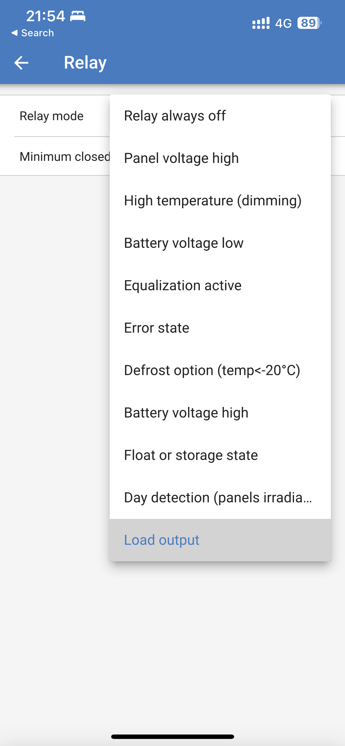
i suspected this must be the case but can’t see such setting available, what am I missing?

0 Likes 0 ·
Dirk-Jan Faber (Victron Energy) avatar image Dirk-Jan Faber (Victron Energy) ♦♦ apple047 commented ·

You are right. The documentation also says that it is not possible yet (https://www.victronenergy.com/live/venus-os:large#solarcharger_mppt_relay).
I thought it had already been added, but was wrong about that.

0 Likes 0 ·
wkirby avatar image wkirby ♦♦ commented ·
If you need extra relays that are for swtching AC powered devices the you could use IP smart plugs and address them directly from a Node-RED.

I use the TP Link Kasa ones, there are nodes available for the smart plugs and smart bulbs to address them directly from Node-RED, no need for internet or any cloud nonsense.

0 Likes 0 ·
wdh2550 avatar image
wdh2550 answered ·

The CerboGX relays can be operated by the "Relay Control" node. See attached
relayflow.txt


relayflow.txt (4.4 KiB)
2 |3000

Up to 8 attachments (including images) can be used with a maximum of 190.8 MiB each and 286.6 MiB total.

silverfox avatar image
silverfox answered ·

I have two Quattro's. Surely Victron has fixed the Multiplus II relay control deficiency so that my 4 relays (2 in each Quattro) can be controlled in Node-Red? But I can't find their controls in my Node-Red. Are they there somewhere?

2 comments
2 |3000

Up to 8 attachments (including images) can be used with a maximum of 190.8 MiB each and 286.6 MiB total.

derrick thomas avatar image derrick thomas commented ·
The MP relays cannot be switched from node red.
0 Likes 0 ·
Alexandra avatar image Alexandra ♦ derrick thomas commented ·

I can also add that they are not likely to be added either. So not a deficiency - a design choice.

The primary relay can be manipulated using the inverter states like you can on the GX or using the front rocker switch.

0 Likes 0 ·
h8mecz avatar image
h8mecz answered ·

Hello guys, I have seen the manuals how to connect Cerbo GX relay to Multiplus II in the means of usage of Power assistent but I would like to know how to connect Relay 2 from Cerbo GX to control Water heating via NodeRED flow. Can I connect Relay 2 from Cerbo GX directly to AUX 1 in Multiplus or it should be connected via Alarm Relay? Thank you guys.

2 |3000

Up to 8 attachments (including images) can be used with a maximum of 190.8 MiB each and 286.6 MiB total.

Alistair Warburton avatar image
Alistair Warburton answered ·

The relay assistant can be easily made to internal Multiplus/Quatro relays to follow an input, I literally did it this morning using AC Out 2 to switch a heating load. you cant do much useful logic with the assistant, so I didn't bother.

I connected the CCGX relay to the Multiplus Aux 1 input so that controlling the CCGX relay, from Node Red, drives AC Out 2 via the relay assistant.

I realize that this doesn't help much with the overall number of outputs, but that is easy to fix, and this gives control over AC Out 2.

Getting more, and or different types of output, is simply a matter of buying a distributed IO module, a Modbus TCP one is generally a good choice because it connects to the GX over Ethernet/WiFi but I am pretty sure, not that I have actually tried , that the Cerbo will support a USB serial adapter as there is a default ..tty/usb port showing up in the config of serial nodes.

Another option is a Modbus TCP to RTU converter and then IO modules on the RS485 RTU bus. I know that is more bits but Ethernet modules are several time the price of RTU versions and a single TCP/RTU gateway will support 127 individual devices/modules, each with potentially thousands of registers, on a single RTU bus, you would literally max out the Cerbo program memory before you ran out of potential hardware IO if you were using modestly wide modules.

A less industrial solution would be MQTT, again Ethernet, less choice of modules and probably very little with Analogue outputs but likely the cheapest option. Think Tasmota or ESP Home on open source hardware... I guess its about how much you want to fiddle.

I am mentioning Analogue output modules because that allows you to spoof a tank/temp/voltage which offers control of stuff not directly available as a writable parameter, modifying export control for example or limiting charge current without having to mess with a configured DVCC setup.

BTW. Charge current can also be limited with an assistant, it can be linked to an analogue Input and driven with your IO module of choice.

If you need Analogue and don't like the price, get a cheap digital output board and go old-school.

R-2R Ladder DAC Digital to Analog Converter (microcontrollerslab.com)

An 8 bit R-2R ladder with a simple totem-pole BJT driver, or an OpAnp, hanging of the end of it will give you 256 discrete signal levels on a low impedance output, no smoothing of or high frequency PWM noise to worry about. 12 Bits, a common IO relay board width gets you 4096 levels or a more sensible range and some unused digital outputs.

Lastly, Node Red can, relatively easily, talk to Alexa / Google Home / Google sheets / Home Assistant... Its a big list. Now you have load shedding possibilities for anything smart, or plugged in to smart sockets, heaters for example, but again an almost endless list of possibilities. You have also added Voice commands to your inputs list and and announcements, even dynamic ones, for literally anything you want you system to tell you.

IO is fun, isn't curtailed by the lack of a relay or two and, in the last 5 years or so, has become almost limitless, for next to no cost, with a bit of out of the box thinking.

Sorry that was a bit off topic, and way longer than I expected, sometimes I wax lyrical about boxes I am avoiding being stuck in.

Hope some of you find it helpful, for everyone else Sorry, its late and I cant sleep.


1 comment
2 |3000

Up to 8 attachments (including images) can be used with a maximum of 190.8 MiB each and 286.6 MiB total.

kurs270 avatar image kurs270 commented ·
Of course all this is true, but it involves adding hardware where software would do the same, which simply doesn't make sense.

What can be done in software should be done in software.

The aux inputs as well as the relais outputs are surely connected to the Multiplus's/Quattro's microprocessor and could of course be logically attached to the VE.bus and hence be readable and writable from the GX device with nodered - as could some additional virtual flags which could in turn be used by the assistants.

Why this has not been done and is apparently not intended to be done... Victron alone knows.

I have a rather similiar problem: In my quattro on my boat, the fan runs all the time, hell alone knows why. I silenced it using the "silence fan" assistant, but now of course charge current is limited by temperature.

I didn't find a way (and probably there is none) to re-activate the fan when the genset is running (making so much noise the fan is no longer audible) except from wiring a relais to the aux input.

So I have to check for the condition in node red, then switch a wifi relais which then closes aux1, so the fan starts and the quattro can charge at full current.

Not a really elegant solution.


0 Likes 0 ·