question

vondie avatar image
vondie asked

BMV-712 Install on multiple batteries

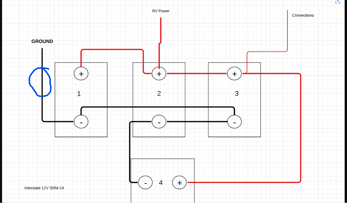
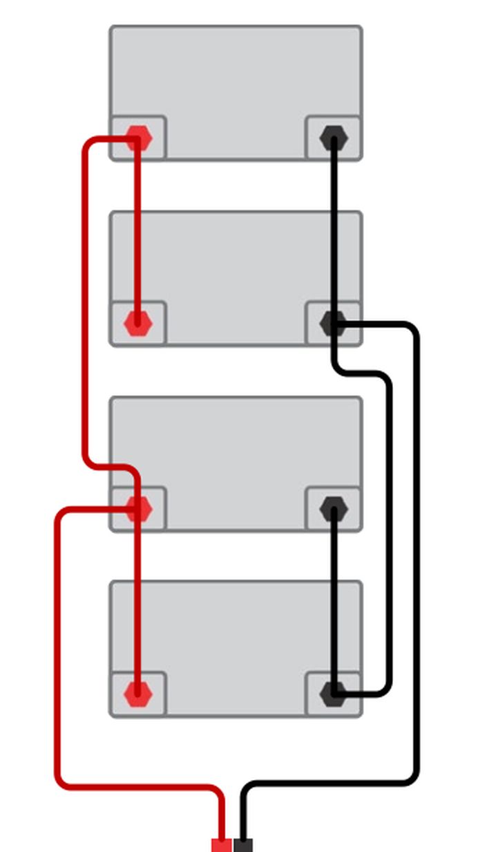
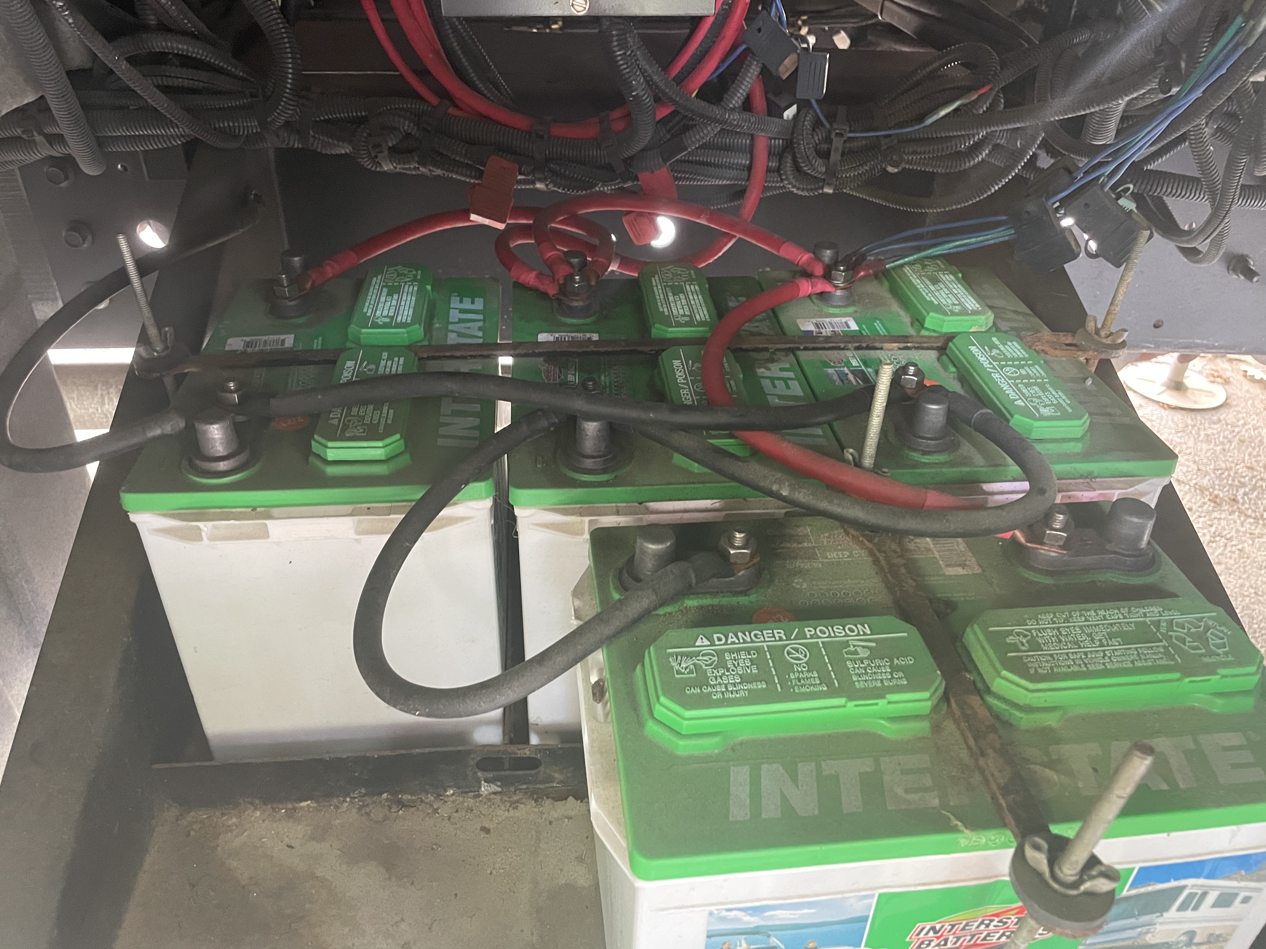
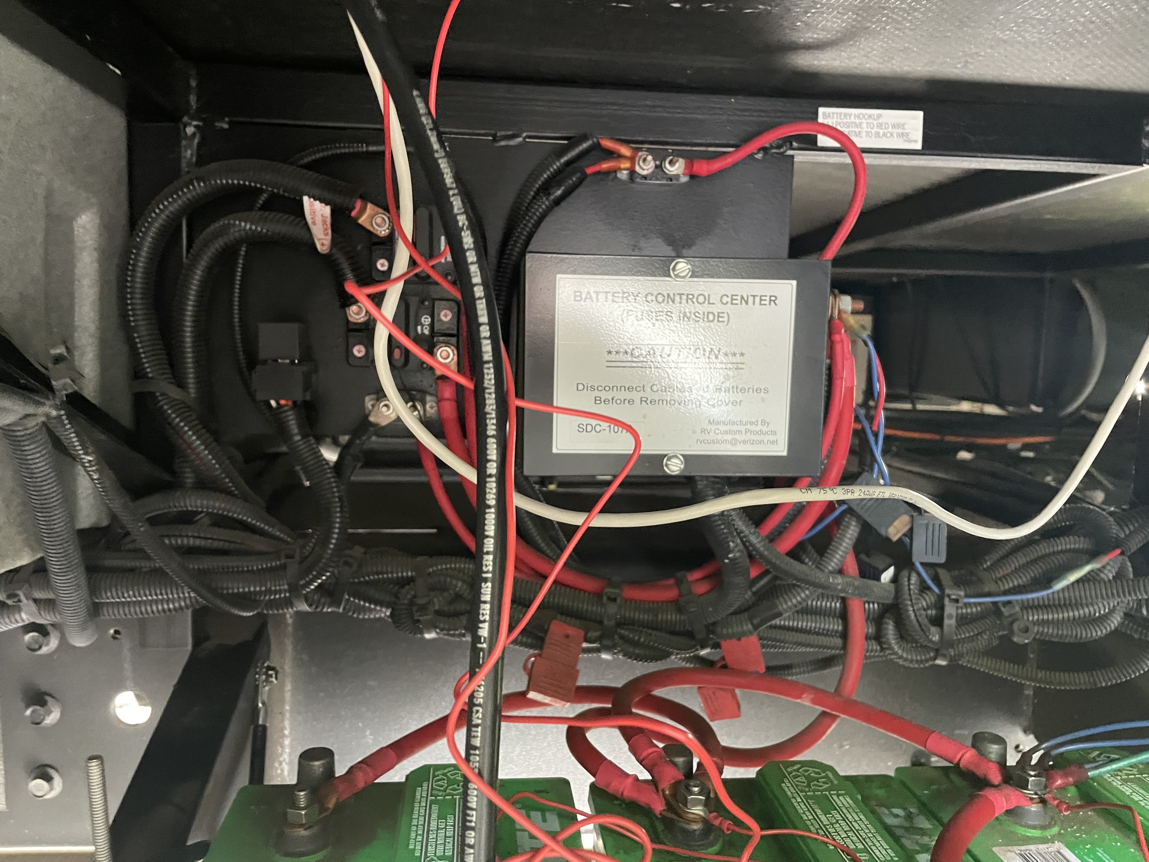
I'm trying to install my BMV-712 on a 2016 Georgetown 364Ts. It has 4 12V house batteries. The coach already has a battery monitor installed. Attached is an image of the layout. I'm not sure where to make my connections? Do i need to remove the existing battery monitor first?


So far I've tried running the battery side of the shunt to battery 1. and I put the ground wire to the load side of the shunt. I also put the small red power cable to battery 3 but do not get power.


Any help on how to connect it would be appreciated!screen-shot-2022-08-07-at-93559-am.png


bmv power consumption
2 |3000

Up to 8 attachments (including images) can be used with a maximum of 190.8 MiB each and 286.6 MiB total.

3 Answers
klim8skeptic avatar image
klim8skeptic answered ·

Location of the shunt should be here.

shunt-location.png

I think that the batteries were meant to be wired up as,

parallel-batts.jpg

but ended up untidy and unbalanced.


shunt-location.png (93.7 KiB)
parallel-batts.jpg (37.1 KiB)
1 comment
2 |3000

Up to 8 attachments (including images) can be used with a maximum of 190.8 MiB each and 286.6 MiB total.

vondie avatar image vondie commented ·
Thank you - This is now working. That is where I had it originally - but I'm not sure why the unit didn't power up. Thanks to all who provided me information!
0 Likes 0 ·
johanndo avatar image
johanndo answered ·

No, you can run both monitors at the same time,

check the fuse on the small red plus wire and make sure you use the proper input on the shunt, there are 2 battery sense wires, one for the main battery (where the plus should go) and onefor the start battery.

7 comments
2 |3000

Up to 8 attachments (including images) can be used with a maximum of 190.8 MiB each and 286.6 MiB total.

vondie avatar image vondie commented ·
Thank you so much- based on the diagram, which battery am I supposed to connect to the shunt?
0 Likes 0 ·
christern avatar image christern vondie commented ·
The point is that everything that uses power from your batteries should be connected via the shunt (BMV) to be measured.

In your drawing on the “ground” side (aka negative) the negative cables to your lamps etc are likely to be connected. Between these cables and the battery’s negative side the shunt should be mounted. The side which says “battery“ on the shunt is to be connected directly to your batteries, battery 1 if your drawing is correct, and all that goes to your loads should be connected to the “load“ side of the shunt. Apart from this there should be a cable from any of your batteries positive side connected to the appropriate connection of the shunt.
If I read your text right this is how you have installed it. Check again that it is properly installed and if so, check that there is voltage on the positive cable by using a multimeter.

0 Likes 0 ·
vondie avatar image vondie christern commented ·
Thats what’s confusing to me - the only things that use power is on the postive side. There are connections on the positive posts of battery 2 and 3. So I should move all those to the load side of the shunt, then connect the battery side back to the positve post?
0 Likes 0 ·
vondie avatar image vondie christern commented ·


14a20371-23af-4f3e-9877-f6f7d5bf2365.jpeg


Here you can see only positive cable power connections. The negative cables only keep the batteries in parallel

0 Likes 0 ·
johanndo avatar image johanndo vondie commented ·

Don't touch the positive side!

You ONLY disconnect EVERYTHING on the Negative side what is NOT A BATTERY, then ALL this cables go to the LOAD SIDE of the SHUNT and ONLY a single thick wire goes between shunt and battery negative. Add the small power wire with the inline fuse to one of the plus poles, regardless which one and you are done.

An electric circuit is called circuit, because the current circulates around from plus via cables, breakers, fuses, switches to minus, all current that leaves the plus returns in the munus and there the shunt trap waits and catches it before it can enter the battery negative on the way home. That simple.

1 Like 1 ·
vondie avatar image vondie johanndo commented ·

this makes sense - but i have no loads on the negative side. Which is causing my confusion. Do i need to install this farther upstream possibly?

0 Likes 0 ·
christern avatar image christern vondie commented ·
Well, if nothing is connected to the negative side you will have absolutely no draw from the batteries. And obviously no shunt will work either.

Check again!!!

(sorry if I seem rude but this is the first thing you need to check!)

0 Likes 0 ·
kevgermany avatar image
kevgermany answered ·


This looks like an odd installation. It's not good to take loads from partway through as it unbalanced the batteries.

Usually with a string like this you would connect the negative of the loads to one end and the positive to the other end. E.g. negatives from loads to battery 1 and positives to battery 4. Same goes for the shunt

1 comment
2 |3000

Up to 8 attachments (including images) can be used with a maximum of 190.8 MiB each and 286.6 MiB total.

vondie avatar image vondie commented ·

Thanks for the response- are you sure it’s serial? I tried to figure that out, serial vs parallel- but i concluded it was parallel because there are no negative to positive connections and the entire rv system is 12v.

But to your point - maybe there is a dc:dc converter- im just not sure why that would be the case. Heres some additional configurations if it helps:


b329d2a5-b3b9-47fd-b77c-de518b9fb32b.jpeg


0 Likes 0 ·

Related Resources

Additional resources still need to be added for this topic