question

davrey avatar image
davrey asked

Pylontech Multiplus Voltage Difference to MPPT not fully Charging ESS only grid feedin

Hello,

I've configured my Pylontech, MultiPlus, ESS etc. as mentioned here: https://www.victronenergy.com/live/battery_compatibility:pylontech_phantom

It's a three phase system, 6,4kwp solar, with 2 mppts. 14,4kwh Pylontech...

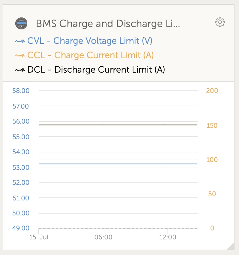
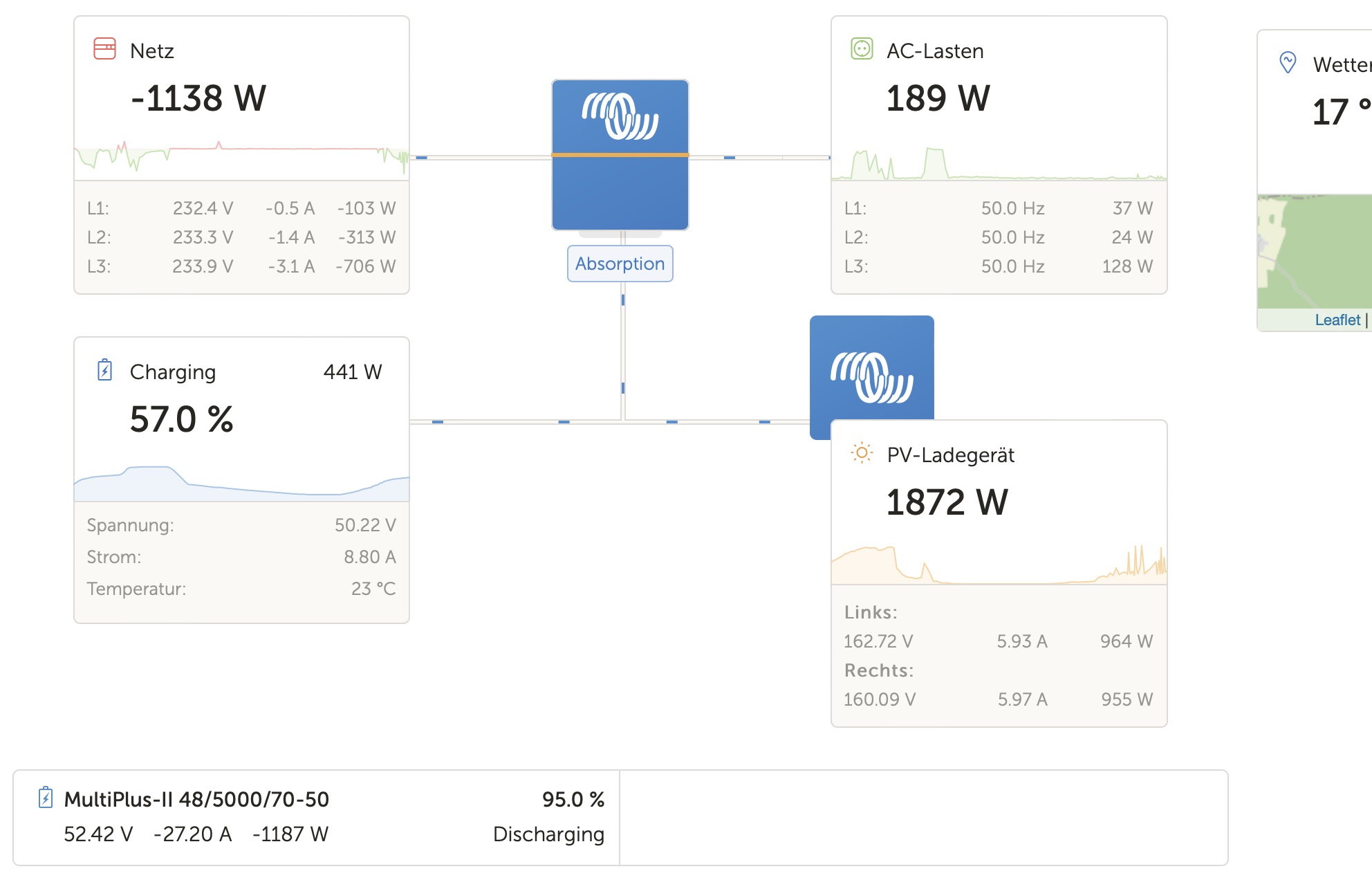
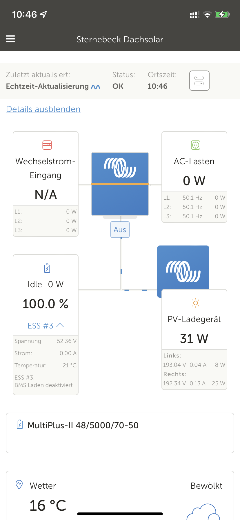
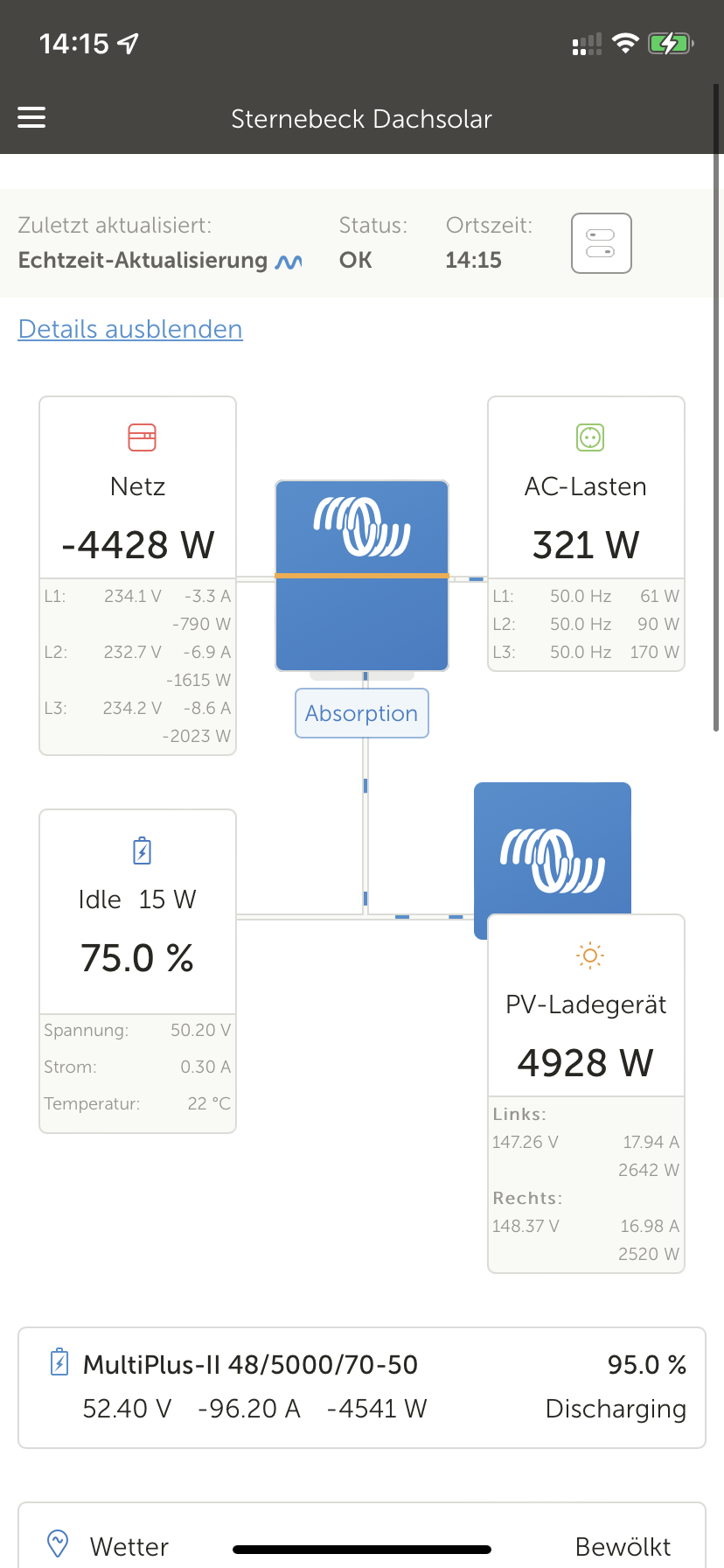
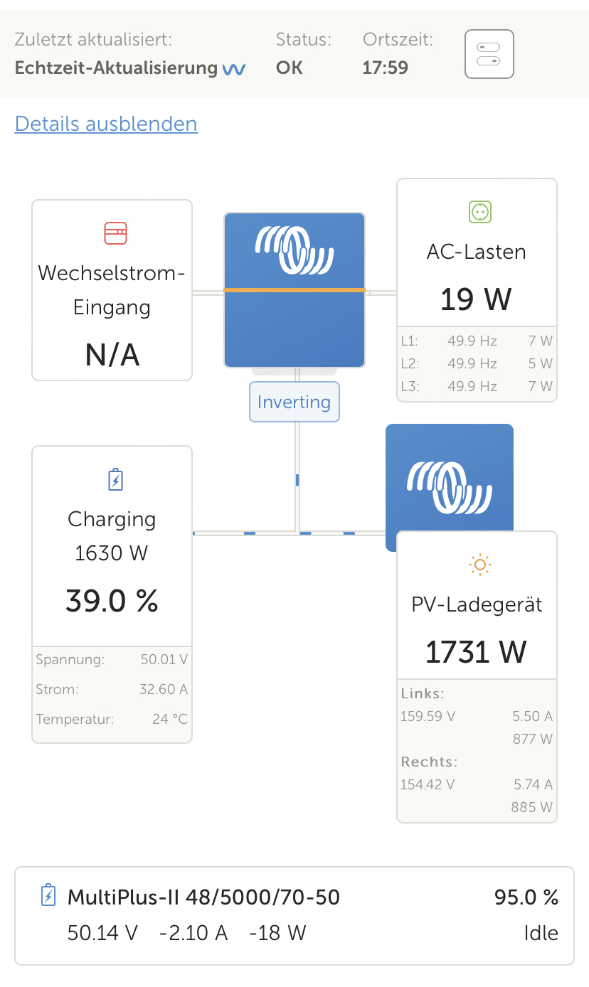
It worked for months without problems. Now it won't "fully" charge the battery. Only when it's SOC is very low it charges till round about 60%SOC. As you can see in the picture it feeds back to the grid although the charge limit allows more current to charge into the batteries.

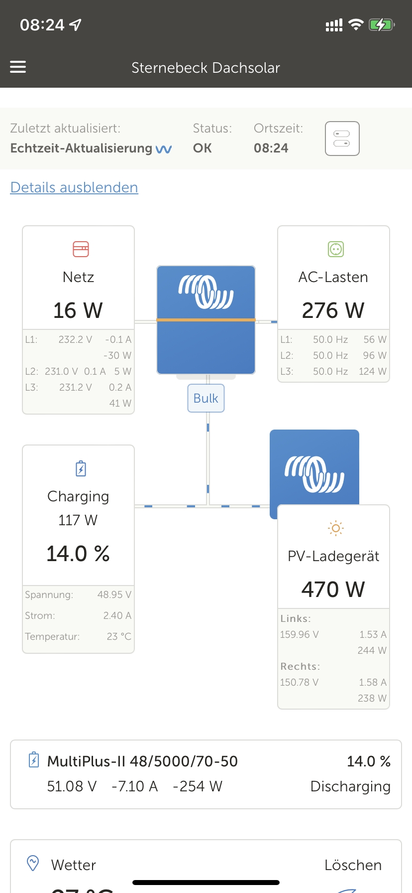
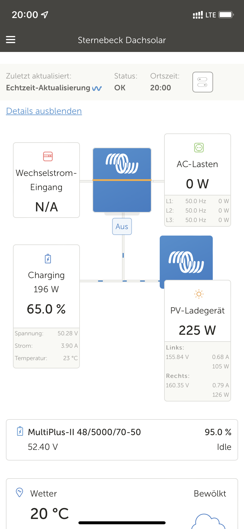
When I turn off the Multis and only the mppts are active the battery is charging well.

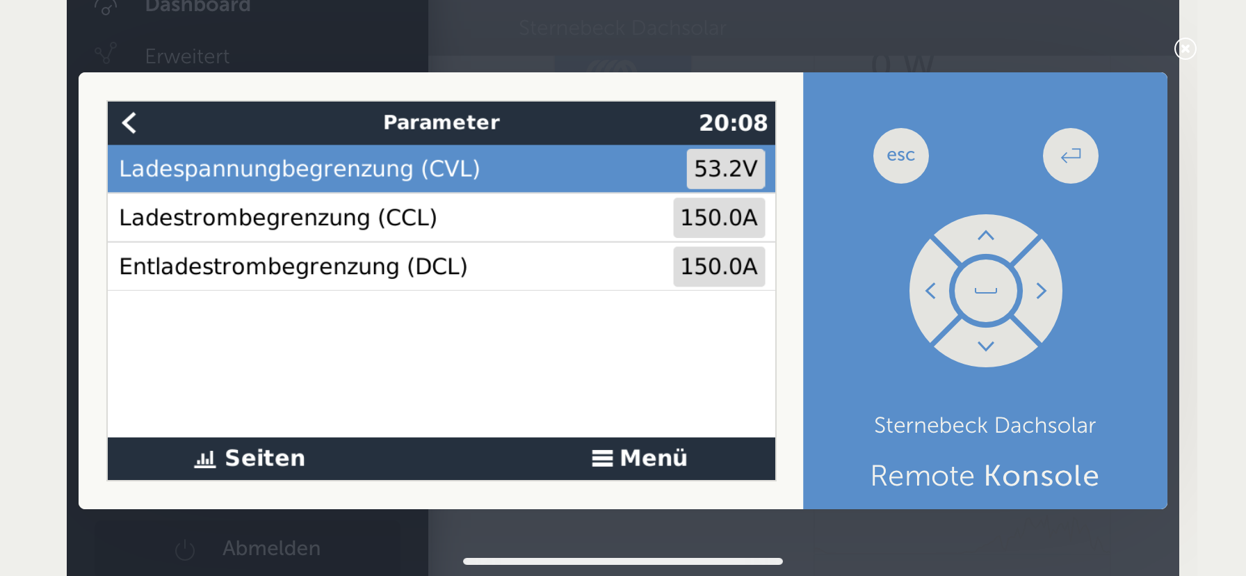
I have switched on the "2nd Batterymon from the Multi" in vrm and as you can see, the SOC and Voltage of the Multi-Bat-Mon are to high. Therefore the Bulk Phase is very short (in this time the batteries are charging with their max Current), then there is the Absorption Phase and the charge current goes down and the feedback goes up. Unfortunately I don't know whether this "Voltage Difference" was from the beginning.

I've measured the voltage on the multi and it's the same as measured from the Pylon BMS.

Now I've updated all Firmware to solve the issue, but it doesn't.


What should I change to make it work again?

Summary:

At all points of the installation (pylon, multi, MPPT connector) you can measure the correct and equal voltage using a multimeter. If you connect to the MPPT via Bluetooth and the Victron app, then you see that this measures the too high voltage. I assume that this wrong (too high value) is also taken in the ESS and therefore the regulation does not work properly.


Sorry for my bad english...


Thanks


DavRey


bms.jpgvrm.jpg


Pylontech
vrm.jpg (209.6 KiB)
bms.jpg (96.0 KiB)
2 |3000

Up to 8 attachments (including images) can be used with a maximum of 190.8 MiB each and 286.6 MiB total.

5 Answers
davrey avatar image
davrey answered ·

new insight:

If the MPPTs are not connected to the GX via Usb, then the values that are read out for the battery voltage (via Bluetooth and app) are also correct.

So the multi must determine the wrong values and contribute to the ESS?! Question: Which multi in a 3 phase system is the master that contributes the battery values?

Tomorrow I'll swap the 3 phases and test whether another multi (as a master?) reads out other values ...

2 |3000

Up to 8 attachments (including images) can be used with a maximum of 190.8 MiB each and 286.6 MiB total.

Alexandra avatar image
Alexandra answered ·

@DavRey

CVL and DCL are requested or set by the Pylontec to the system.

Where are the mppts connected? It is likely the terminal voltage is higher at the inverter due to the injection of the voltage from them.

You are feeding back so terminal voltage being higher is also expected. As it is feeding dc voltage back through to ac. Also the battery voltage is shown on your picture at 50.33v so not actually a problem since they are not being overcharged.


3 comments
2 |3000

Up to 8 attachments (including images) can be used with a maximum of 190.8 MiB each and 286.6 MiB total.

davrey avatar image davrey commented ·

Based on my other additions. Do you have any more advice?

0 Likes 0 ·
Alexandra avatar image Alexandra ♦ davrey commented ·
@DavRey

Do you use a torque wrench to tighten all the battery an ac terminals.

Resistance changes voltage and current, if they are different tightness then that could be a factor, also cable lengths do they match and resistance, what is your DC ripple?

0 Likes 0 ·
davrey avatar image davrey Alexandra ♦ commented ·

During the first setup, I tightened all terminals equally with a wrench. All cables have the same length. Everything has also worked in this constellation for months. The same voltage can be measured at all terminals with a multimeter.

So far I have set the new configurations using Remote VRM. I will look tomorrow in the VEConfigure directly for the DC ripple.


0 Likes 0 ·
davrey avatar image
davrey answered ·

Hello and thank you for the answer. I would like to contribute some more facts and answer your question. The MPPTs are connected to the Lynx Busbar. All devices are connected to it.

I know that CVL and DCL are requested by the Pylontech. But, as you can see from the screenshots, Pylontech BMS requests more voltage and current than it actually gets. Even if the inverter is not feeding in or charging voltage, VRM portal shows/measures higher voltage than actually measured by multimeter.

Even if you disconnect the grid and no loads are connected to the multis, a voltage too high is displayed.

If you switch off the three Multis at the hardware switch, then after a few seconds the ESS will set a new measuring device. In that case, it is then the MPPTs themselves, which then measure the correct voltage and then charge the battery without error. That is Until approx 97% SOC then it takes longer, but this is normal and expected.

In all constellations the voltage measured by the BMS is correct. Only the multis measure the voltage that is too high. I suspect that this too high voltage is taken in the overall system to regulate the charge. However, since it is 2 V higher, the battery can not charge properly.


Low SOC, everything seems to be OK. Also the SOC from the Batteriemonitor from the multis and the BMS are the same,...everything-seems-to-be-ok-with-o-low-soc.png


Voltage Measured by Multis is higher than BMS Voltage. Here are nor loads Connected. Grid is disconnected.

grid-and-load-disconnected.png


When all Multis are switched of, charging the batteries is working well. Because now the Voltage measured from the mppts is taken

loading-finished-with-multis-switched-of.png


The SOC form the Batterie monitor from the Multis and from the BMS are different.

multi-on-ess-disabled-mppts.png


That's the problem. Instead of charging the batteries the Currents is feed back to the grid.

grid-feed-in-an-no-more-charge-of-batteries.png

...although the battery still wants to charge...

cvl-ccl-from-pylon.png


2 |3000

Up to 8 attachments (including images) can be used with a maximum of 190.8 MiB each and 286.6 MiB total.

davrey avatar image
davrey answered ·

Addition:

I have disconnected inputs and output of the multis. Then I swapped L1 and L3 in VEConfigure and reloaded the ESS assistant into all multis. As you can see, the "new" L1 Multi measures the correct voltage, sends it to the system and it regulates and charges correctly.

Can I assume that the other multi is defective and determines an incorrect voltage, or are there other things that I should test before?

Why is it not possible to set which multi determines the voltage? Or why is it not possible to select the MPPT as a voltmeter?

Could I install another Victron component, which then acts as a voltmeter?

l1-and-l3-switched.jpeg


2 |3000

Up to 8 attachments (including images) can be used with a maximum of 190.8 MiB each and 286.6 MiB total.

davrey avatar image
davrey answered ·

Update: Now the second Multi shows the same behaviour. He now also measures a too high voltage :-( You can find some other posts in other forums with the same problem. But unfortunately without a solution.


I tried to disable the battery Monitor in the Multis. No success.

I tried to disable the charger in the Multis. My hope was that then the MPPT or BMS is used as voltage sensor. Unfortunately not. No success.

Am I the only one with this problem ? :-(

2 |3000

Up to 8 attachments (including images) can be used with a maximum of 190.8 MiB each and 286.6 MiB total.